12
5. To remove control panel assembly and PCB
1) Unplug the oven or turn off the power at the main power supply.
2) Remove the vent grille mounting 3 screws and open the door.
3) Slide the grille air to the left, then pull it straight out.
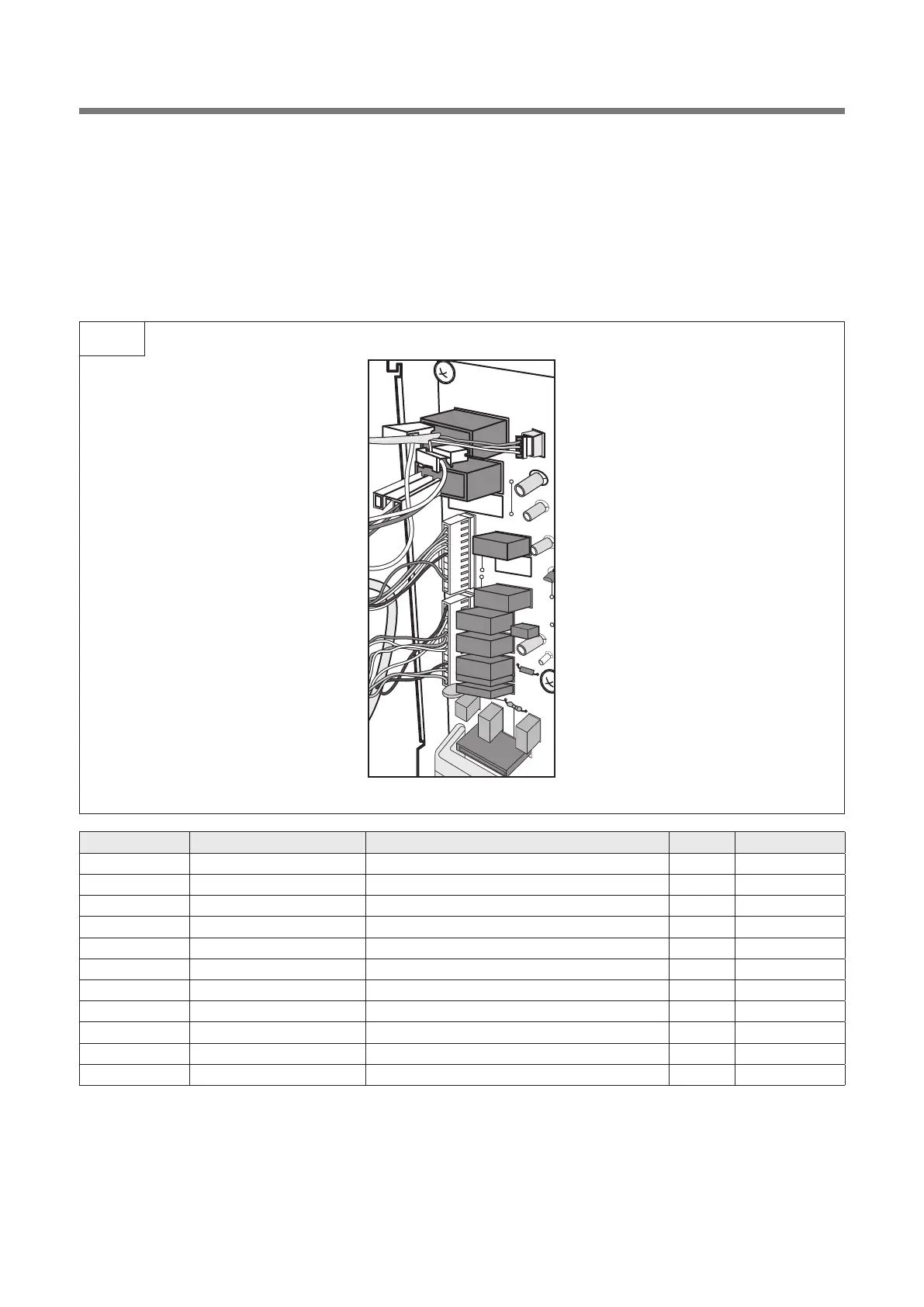
4) Remove a screw secured to the control panel assembly.
5) Pull out the connectors from the PCB.
6) Remove 5 screws of PCB.
7) Reverse the above steps for reassembly.
A00
1) Remove the screw which secure the control panel and draw forward the control panel assembly.
2) Remove 5 screws which secure the PCB assembly.
3) Pull out the PCB assembly from the control panel.
4) Disconnect membrane tail from the connector of the PCB assembly.
5) Remove the PCB from the control panel as.
6) Remove the membrane, lever door open, spring button and button door open from the control panel.
7) Reverse the above steps for reassembly.
NO PART CODE PART NAME Q'TY REMARK
B01 9KC35116-0043300 DECORATOR BUTTON 1
B02 9KC35169-0030200 BUTTON DOOR OPEN 1
B03 9KC441G430171 SPRING DOOR BUTTON 2
B04 9KC35116-0043200 DECORATOR C-PANEL *U 1
B05 9KC35116-0043100 DECORATOR C-PANEL *T 1
B06 9KC65192-0030000 SWITCH MEMBRANE 1
B07 9KC35167-0110800 CONTROL-PANEL 1
B08 9KC35168-0000500 BACK-PLATE AS 1
B09 9KC35137-0003100 LEVER DOOR OPEN 1
B10 9KC40303-0115400 MWO PCB MAIN ASSY 1
B11 9KC7122401211 SCREW TAPPING 4
 Loading...