SSC3088AS
32
Screws for securing
the thermistor (engine)
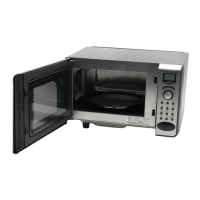
Engine unit
Harness of the
thermistor (engine)
Hole of the engine cover
Engine unit
Harness of the
thermistor (engine)
The braided glass tube (white tube part)
should protrude from the engine cover.
4. What to do after replacement of the engine unit
After installing a new engine unit, 1. Please perform the steamed food
operation. When a new engine unit is installed, if the steamed food op-
eration is not carried out, the engine unit will not work normally.
1. Steamed food operation
1) Inject water into the water tank until it reaches water level 2.
2) Press the key “Manual setting”
3) Select “Steamed food”.
4) Set the operation time to 15 minutes.
5) Press the key “Warm-up start”.
6) After the operation comes to an end, repeat the procedure from
step 1) to step 5). (Repeat the 15-minute steamed food opera-
tion two times.)
Note: Do not stop operation halfway. If it is stopped, water will
be left in the tube pump K. So, please conduct forced
drainage in test mode 6.
●After installing the engine unit, please confirm that the
pump tube E is not obstructed where the tube of the en-
gine unit is installed.
[Reason for steamed food operation]
Although the interior of the engine unit has a special
coating to protect its surface, it has a water-repelling
property. Therefore, in case of a new engine unit, water
will not attach to the internal surface of the engine unit
and it is hard to transmit the heat on the engine unit
surface to the water even if the engine unit is heated.
Water vapor cannot be generated and the engine unit
is overheated. The thermistor (engine) detects abnor-
mal temperature and the operation of the engine unit
is stopped.
Hydrophilia of the internal surface of the engine unit
can be improved by performing the steamed food
operation and the thermal transmission will become
normal.
[19] Circulation the unit K and thermistor (oven)
1. How to remove the thermistor (oven)
1) Remove the side cover R, the side cover L, the exhaust cover
and the cabinet. [3] Reference
2) Remove the left/right reinforcing AG and the rear plate. [17]
Reference
3) Remove the harness from the D motor (intake) and the damper
SW (intake).
4) Remove the harness from the intake duct cover top and the
hook of the intake duct top.
5) Remove the screws (5x) which fasten the intake duct top to the
rear of the heat insulating plate, the bottom of the intake duct,
the left of the heat insulating plate and the intake duct cover and
remove the intake duct top.
6) Remove the thermistor holder from the circulation unit K. (1
screw)
Nuts x2
Thermistor
Circulation unit K
7) Remove the thermistor (oven) from the thermistor holder. (1
screw)
8) Remove the thermistor (oven) from the THM packing.
Note: When fitting the thermistor (oven) to the thermistor holder,
insert the thermistor (oven) into the THM packing.
Thermistor (oven)
Screw
Thermistor
holder
THM packing
2. How to remove the circulation unit K
1) Remove the side cover R, the side cover L, the exhaust cover and the
cabinet. [3] Reference
2) Remove the left/right reinforcing AG and the rear plate. [17]
Reference
3) Remove the thermistor holder. (Refer to 1. How to remove the
thermistor (oven))
4) Remove the controlling harness from the circulation unit K.
5) Remove the screws (8x) which fasten the circulation unit to the
oven DK.
6) Remove the circulation unit K from the oven DK.
Note:
Install the circulation unit K while placing the connector on
the rear plate.
[20] Sirocco motor (right)
1. Remove the side cover R, the side cover L, the exhaust cover and
the cabinet. [3] Reference
2. Remove the left/right reinforcing AG and the rear plate. [17] Refer-