9-12
VL-PD3S/H/E VL-PD3S/H/E
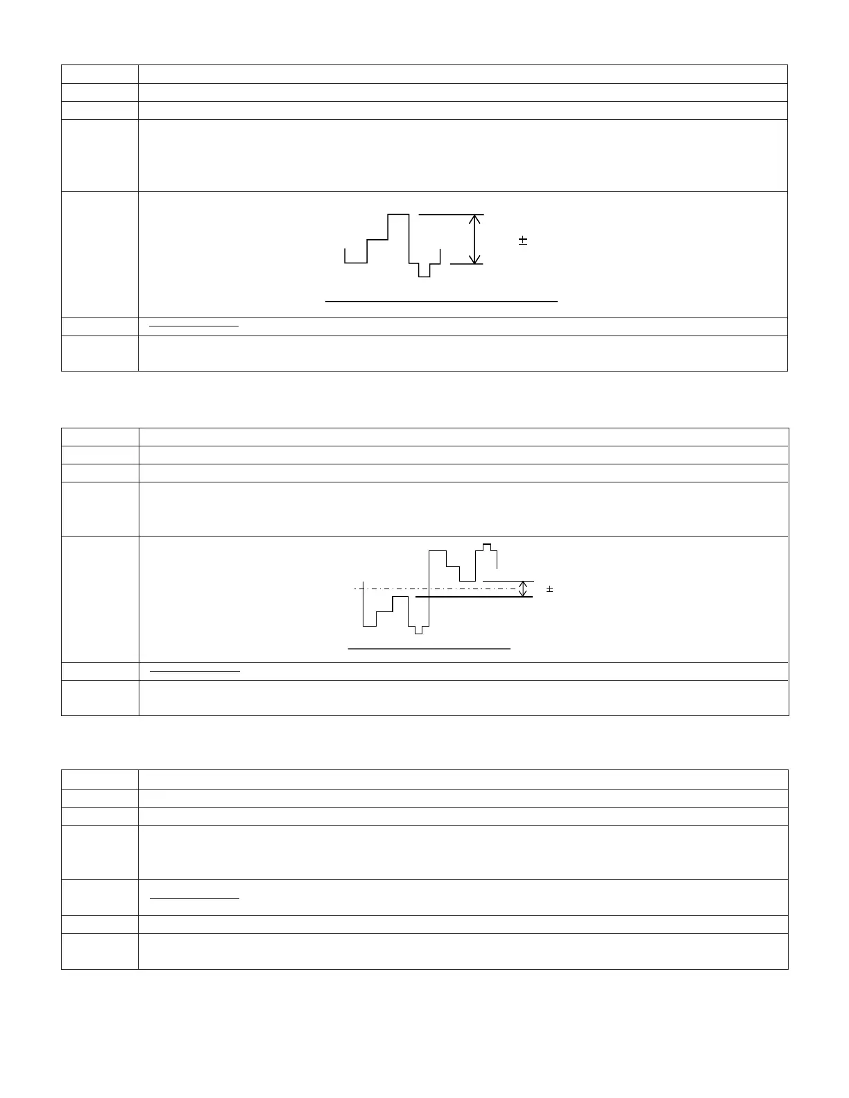
3. VF contrast adjustment
Test point TL8811 (VG)
Address VCR ADJ 45
Mode VCR AV input
Procedure 1) The input signal must be 3-step wave.
2) Connect TL8825 (IC8800 pin 53) to GND.
3) Change the address 41/42 to 00.
4) Adjust the pedestal -100% interval of wave form of TL8811 to the specified level.
Adjustment 1.0 ± 0.1Vp-p
rating
Remark
Examples • During E
2
PROM (IC703) replacement.
• During IC8800 replacement.
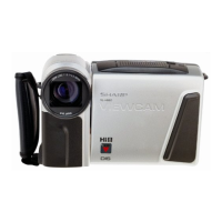
4. VF γ 1 adjustment
Test point TL8811 (VG)
Address VCR ADJ 42
Mode VCR AV input
Procedure 1) The input signal must be 3-step wave.
2) Connect TL8825 (IC8800 pin 53) to GND.
3) Adjust the pedestal -100% interval of wave form of TL8811 to the specified level.
Adjustment 3.1 ± 0.1Vp-p
rating
Remark
Examples • During IC703 (E
2
PROM) replacement.
• During IC8800 replacement.
5. VF sub bright R/B adjustment
Test point View Far panel area
Address VCR ADJ 44 (R) VCR ADJ 43 (B)
Mode VCR AV input
Procedure 1) Feed 40% white signal to the AV input jacks and the standard monitor.
2) Adjust the tone of the colour with the VCR ADJ addresses 43 and 44 until it becomes the same as that of the
standard monitor.
Adjustment
rating
Remark Make this adjustment after 5-minute or longer aging.
Examples • During IC703 (E
2
PROM) replacement.
• During IC8800 replacement.
GND
1.0 0.1 Vp-p
GND
Sig.center 3.1 0.1 Vp-p