1. REMOVAL OF MECHANICAL PARTS
AND P.C. BOARDS
CAUTION
Be careful not to remove the FFC cable forcibly, because
the FFC cable may be damaged.
1-1: STAND ASS'Y
Refer to Fi
. 1-1
1. Remove the 4 screws
1
.
2. Remove the Stand Ass'
in the direction of arrow.
DISASSEMBLY INSTRUCTIONS
(1)
(1)
Back Cabi Ass'y
Stand Ass'y
(1)
(1)
(1)
(A)
(2)
Operation PCB
(1)
(1)
(1)
(2)
Back Cabi Ass'y
(1)
Cover Jack Ass'y
Remocon PCB
(2)
(2)
(2)
(2)
(2)
(2)
(2)
(2)
(2)
(2)
(2)
(2)
(2)
(2)
(2)
(2)
(2)
(2)
(3)
(B)
(C)
(D)
(4)
(4)
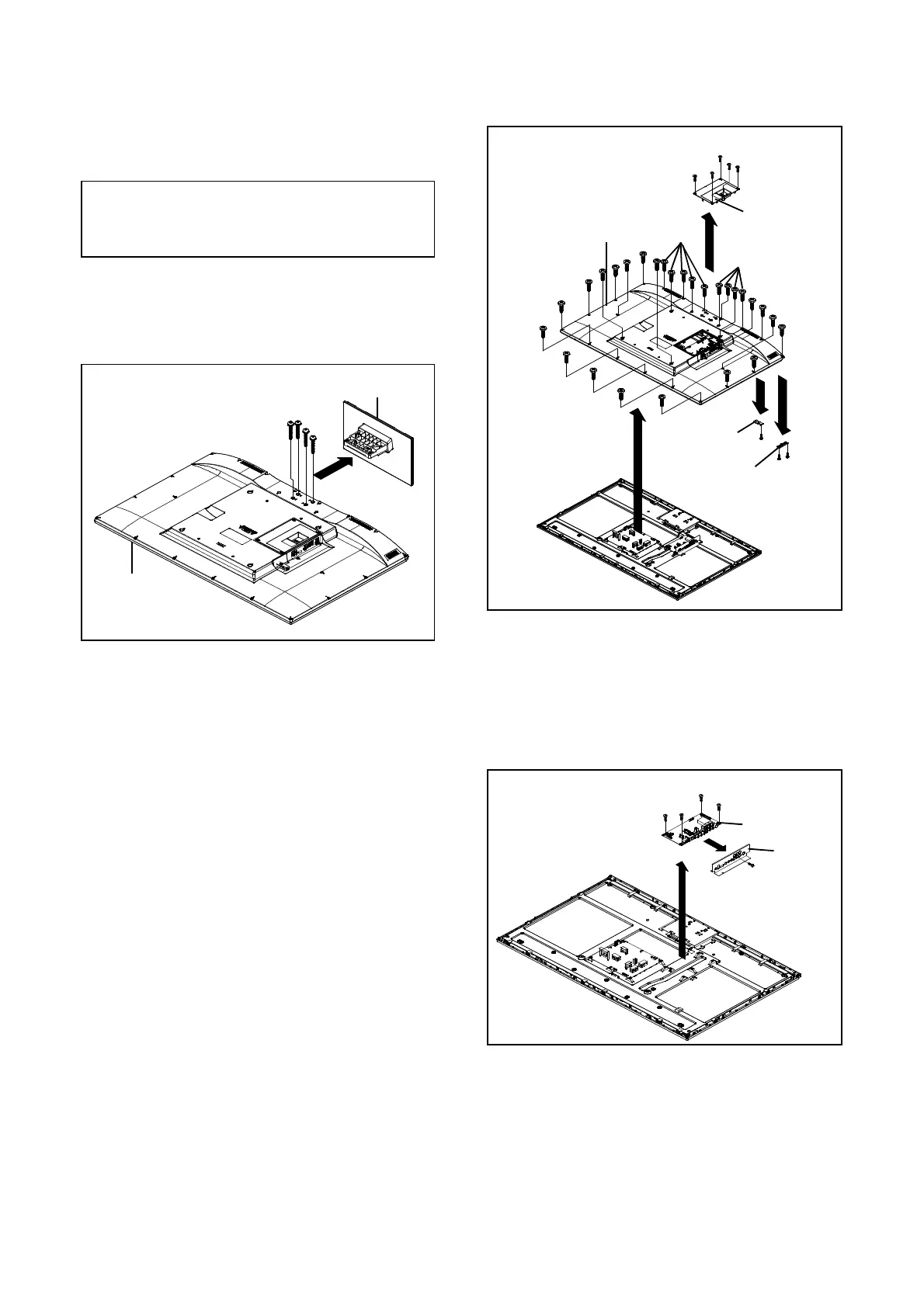
1-3: MAIN UNIT
Refer to Fi
. 1-3
1-2: BACK CABI ASS'Y/REMOCON PCB/OPERATION PCB 1. Remove the screw
1
.
(Refer to Fig. 1-2) 2. Remove the 4 screws (2).
3. Disconnect the following connectors:
1. Remove the 5 screws
1
.
CP3806, CN12, CN18
.
2. Remove the Cover Jack Ass'
in the direction of arrow
A
. 4. Remove Plate Jack in the direction of arrow
A
.
3. Remove the 27 screws
2
. 5. Remove the Main Unit in the direction of arrow
B
.
4. Remove the Back Cabi Ass'
in the direction of arrow
B
.
5.
Disconnect the followin
connectors:
CP2201
CP2202
.
6. Remove the screw
3
.
7. Remove the Remocon PCB in the direction of arrow (C).
8. Remove the 2 screws
4
.
9. Remove the Operation PCB in the direction of arrow (D).
Fig. 1-3
Fi
. 1-1
Plate Jack
Main Unit
(1)
Fi
. 1-2
(2)
(2)
(2)
(2)
(A)
(B)
B1-1