XE-A302U HARDWARE DESCRIPTION
– 9 –
5-3. KEYSCAN MATRIX
PENDING
Others
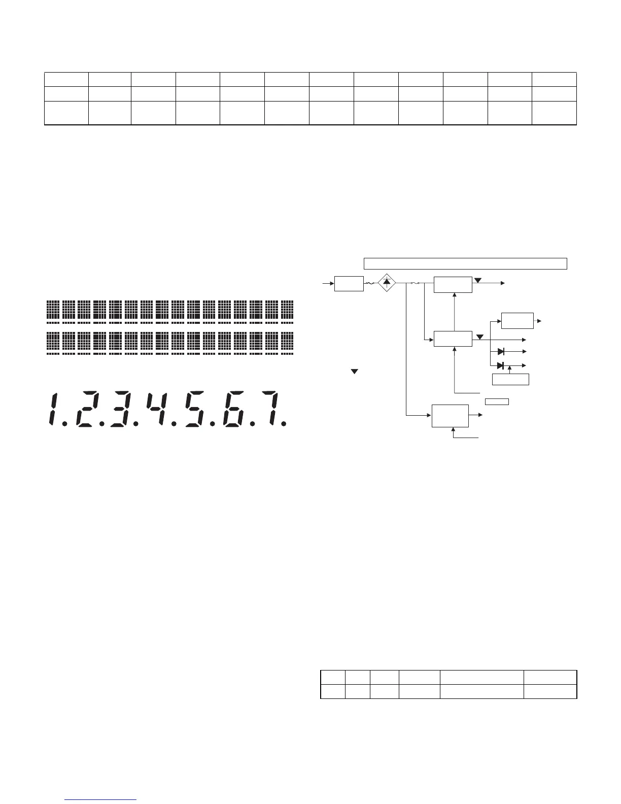
5-4. DISPLAY (PENDING)
The machine has an LCD display, 5 x 7 dots, 2 lines, 16digits, at the
front side and a 7-digit LED at the pop-up side
FRONT:
POP UP:
• Display DIGIT signal
The above ST0 ~ ST6 are display digit signals.
ST0: 1st digit ~ ST6: 7th digit
• Display SEGMENT signal
The LED segment signal is outputted by writing SEGMENT data in
the /CS3 space.
Correspondence of DATA ~ SEGMENT
D0 ~ D6 3 a ~ g
D7 3 DP
6. POWER SUPPLY
7. REWRITING FLASH MEMORY
IPL from EP-ROM: After IPL SW is set to ON side the program is
started from EP-ROM by turning on the power.
The program on EP-ROM is transferred to flash
ROM by switching the banks through S-RAM.
IPL from COM: Data from the PC is written to flash ROM through
the COM port. (Max. 38.4 kbps)
8. DRAWER
The machine has a 1 channel of drawer port.
No open sensor is provided.
The driving time for the DRAWER solenoid are as follows:
50ms (max) 45ms (min)
CPU STO ST1 ST2 ST3 ST4 ST5 ST6 ST7 ST8 ST9
MODE P90 SRV PGM Time REG MGR X1/Z1 X2/Z2 KEYBD
Others P91 PF HEAD
UP
PE DRAWER
OPEN
RS-232
CI1
KEYBD : 1=Normal Keyboard/0=Flat Keyboard
HEAD UP : 1=Up/0=Down
PE : 1=Paper End/0=Paper Not End
DRAWER OPEN : Reserved (1=Open/0=Close)
RS-232 CI1 :
No. I/O PORT Function Signal Name Initial value
27 OUT P73 Drawer Drive Signal L
LM2574
+ Tr.
Drawer
VLED 5.7V
VCC
PRINTER HEAD MOTOR
VDD
VDRW 24V
5V
5V
VH 8V
Batterry
TRANS.
PQ1CG203
PQ1CG203
(MODE SW, /POFF, CPU P105)
BA00ASFP
VLMP 4.3V
LCD
After detection of /POFF, power interruption must be executed within 10ms.
/POFF
detection point
ON/OFF control (MODE SW)
ON/OFF control
Winding motor