– 19 –
XL-30H/30W
SW651 VOLTAGE SELECTOR 220-240V
(XL-30W Only)
NSW801 PICKUP IN ON—OFF
SW700 JOG ON—OFF
SW709 ON/STAND-BY ON—OFF
SW710 CLOCK/TIMER/SLEEP ON—OFF
SW711 TUNING UP ON—OFF
SW712 PLAY/CD PAUSE ON—OFF
SW713 VOLUME SELECT ON—OFF
SW721 MEMORY/SET ON—OFF
SW722 BASS/TREBLE ON—OFF
• The indicated voltage in each section is the one measured
by Digital Multimeter between such a section and the chas-
sis with no signal given.
1. In the tuner section,
( ) indicates AM
< > indicates FM stereo
2. In the main section, a tape is being played back.
3. In the deck section, a tape is being played back.
( ) indicates the record state.
4. In the power section, a tape is being played back.
5. In the CD section, the CD is stopped.
• Parts marked with “ ” ( ) are important for
maintaining the safety of the set. Be sure to replace these
parts with specified ones for maintaining the safety and
performance of the set.
NOTES ON SCHEMATIC DIAGRAM
• Resistor:
To differentiate the units of resistors, such symbol as K and
M are used: the symbol K means 1000 ohm and the symbol
M means 1000 kohm and the resistor without any symbol is
ohm-type resistor. Besides, the one with “Fusible” is a fuse
type.
• Capacitor:
To indicate the unit of capacitor, a symbol P is used: this
symbol P means micro-micro-farad and the unit of the
capacitor without such a symbol is microfarad. As to
electrolytic capacitor, the expression “capacitance/withstand
voltage” is used.
(CH), (TH), (RH), (UJ): Temperature compensation
(ML): Mylar type
(P.P.): Polypropylene type
• Schematic diagram and Wiring Side of P.W.Board for this
model are subject to change for improvement without prior
notice.
REF. NO
DESCRIPTION
POSITION POSITIONREF. NO
DESCRIPTION
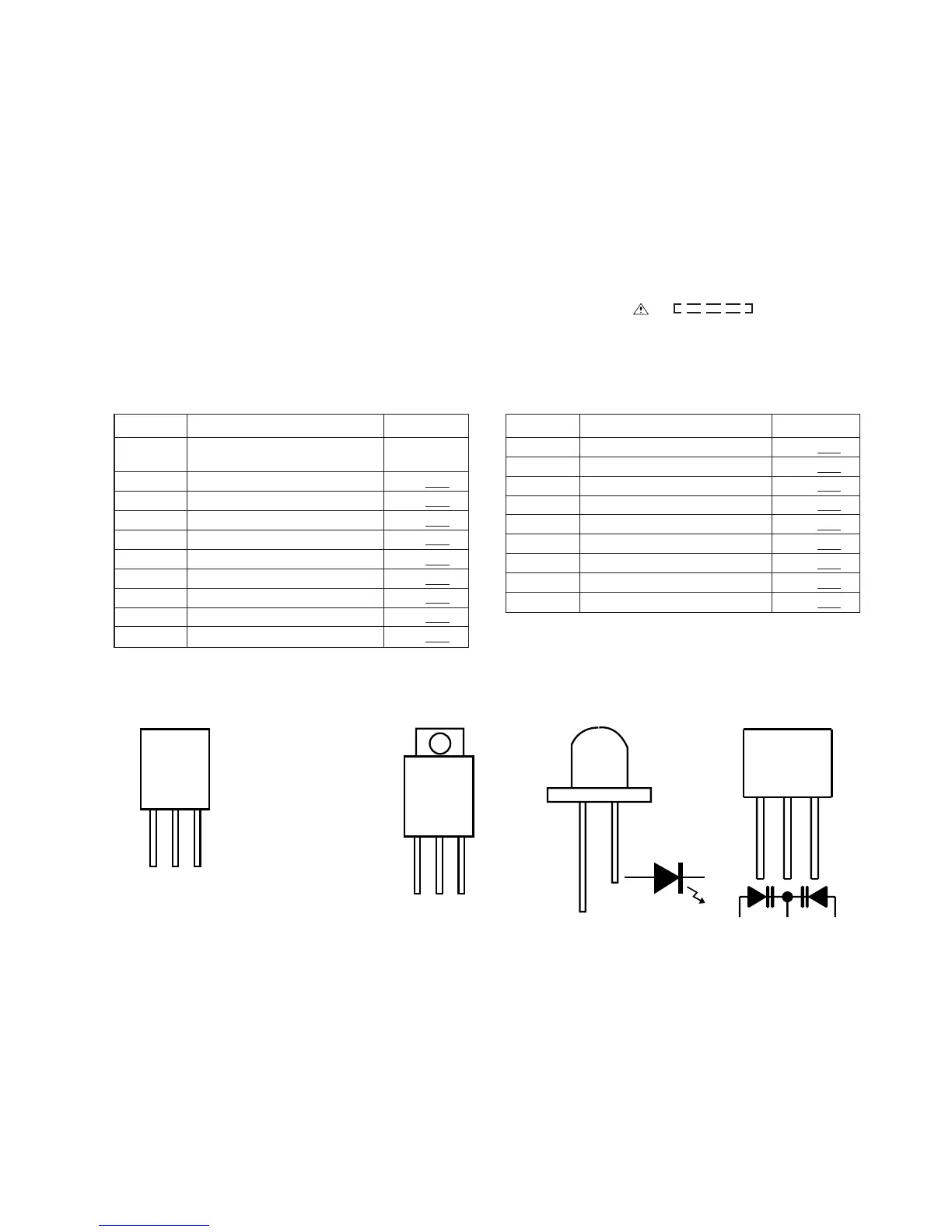
Figure 19 TYPES OF TRANSISTOR AND LED
SW723 BAND ON—OFF
SW724 REC. PAUSE ON—OFF
SW725 STOP/CLEAR ON—OFF
SW726 TUNING DOWN ON—OFF
SW727 FUNCTION ON—OFF
SW728 VOLUME JOG ON—OFF
SW801 OPEN/CLOSE ON—OFF
SW901 FOOL PROOF ON—OFF
SW902 CAM ON—OFF