XL-MP130
2 – 1
AudioXL-MP130Service ManualXLMP130MarketE
CHAPTER 2. ADJUSTMENTS
[1] ADJUSTMENT
1. MECHANISM SECTION
• Driving Force Check
• Torque Check
2. TUNER SECTION
fL: Low-range frequency
fH: High-range frequency
• AM IF/RF
Signal generator: 400 Hz, 30%, AM modulated
• FM RF
Signal generator: 1 kHz, 40 kHz dev., FM modulated
• FM IF
Signal generator: 10.7MHz FM modulated
• Tape Speed
3. CD SECTION
• Adjustment
Since this CD system incorporates the following automatic adjust-
ment functions, readjustment is not needed when replacing the
pickup. Therefore, different PWBs and pickups can be combined
freely.
Each time a disc is changed, these adjustments are performed
automatically. Therefore, playback of each disc can be performed
under optimum conditions.
Items adjusted automatically
1) Offset adjustment (The offset voltage between the head amplifier
output and the VREF reference voltage is compensated inside the
IC.)
* Focus offset adjustment
* Tracking offset adjustment
Torque Meter Specified Value
Play: TW-2111 Over 80 g
Torque Meter Specified Value
Play: TW-2111 30 to 80 g.cm
Fast forward: TW-2231 70 to 180 g.cm
Rewind: TW-2231 70 to 180 g.cm
Test Stage Frequency Frequency
Display
Setting/
Adjusting
Parts
Instrument
Connection
AM IF 450 kHz 1,602 kHz T351 *1
AM Band
Coverage
— 531 kHz (fL): T306
1.1 ± 0.1 V
*2
AM Tracking 990 kHz 990 kHz (fL): T303 *1
*1. Input: Antenna Output: TP302
*2. Input: Antenna Output: TP301
Test Stage Frequency Frequency
Display
Setting/
Adjusting
Point
Instrument
Connection
FM Band
Coverage
— 87.50 kHz T301 (fL):
1.3 ± 0.1 V
*1
FM RF 98.00 MHz
(10-30 dB)
98.00 MHz L312 *2
*1. Input: Antenna Output: TP301
*2. Input: Antenna Output: Speaker terminal
Test Stage Frequency Frequency
Display
Setting/
Adjusting
Point
Instrument
Connection
IF 10.7 MHz 98 MHz T302
(Turn the
core of trans-
former T302
fully counter-
clock wise)
*1
*1. Input: Antenna Output: TP301
Test Tape Adjusting
Point
Specified
Value
Instrument
Connection
Normal
speed
MTT-111 Variable
Resistor in
motor.
3,000 ± 30 Hz Speaker Ter-
minal (Load
resistance: 6
ohms)
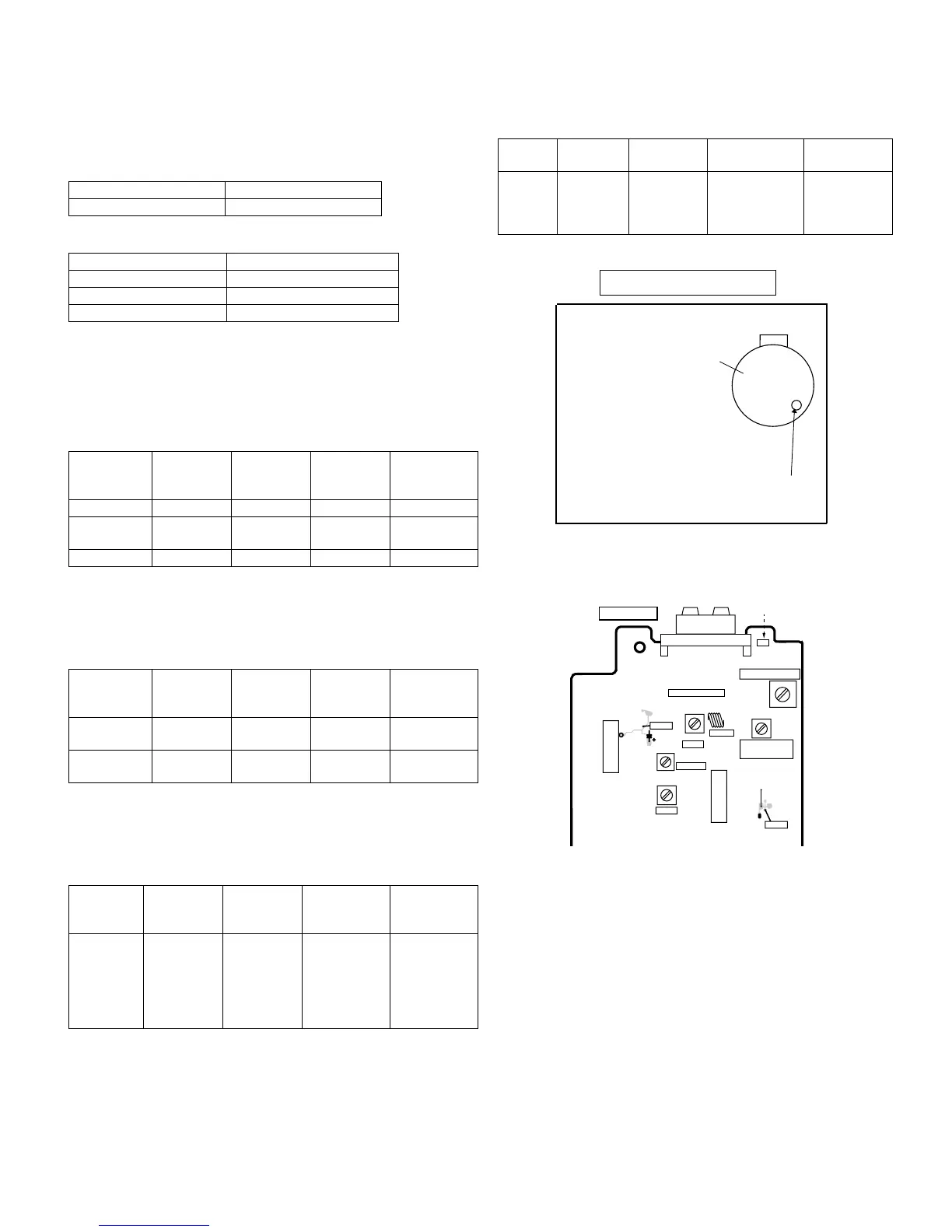
Figure 1
Figure 2 ADJUSTMENT POINTS
TAPE MECHANISM
Tape
Motor
Variable Resistor in motor
AM
LOOP
ANTENNA
IC302
T351
T301
IC303
T303
T306
T302
L312
CNP301
SO302
IC301
TP302
TP301
AM TRACKING fL
AM BAND
COVERAGE fL
AM IF
FM RF
FM IF
FM OSC
FM ANTENNA
TERMINAL
TUNER PWB-C
20
R356
C393
 Loading...