XL-MP130
3 – 3
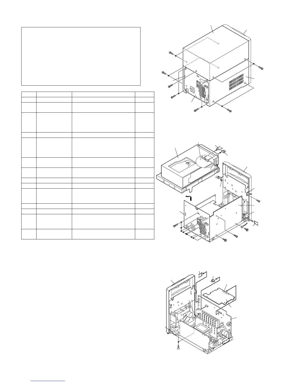
[2] DISASSEMBLY
Note 1:
After removing the connector for the optical pickup from the connector,
wrap the conductive aluminium foil around the front end of the connec-
tor so as to protect the optical pickup from electrostatic damage.
Caution on Disassembly
Follow the below-mentioned notes when disassembling the unit and
reassembling it, to keep it safe and ensure excellent performance:
1) Take cassette tape and compact disc out of the unit.
2) Be sure to remove the power supply plug from the wall outlet
before starting to disassemble the unit.
3) Take off nylon bands or wire holders where they need to be
removed when disassembling the unit. After servicing the unit,
be sure to rearrange the leads where they were before disas-
sembling.
4) Take sufficient care on static electricity of integrated circuits and
other circuits when servicing.
STEP REMOVAL PROCEDURE FIGURE
1 Top Cabinet 1. Screw.............................(A1) x5 1
2 Side Panel (Left/
Right)
1. Screw.............................(B1) x8 1
3 CD Changer unit 1. Screw.............................(C1) x2
2. Hook...............................(C2) x2
3. Socket............................(C3) x1
4. Flat Cable.......................(C4) x1
2
4 Rear Panel 1. Screw.............................(D1) x9 2
5 Front Panel 1. Screw.............................(E1) x3
2. Flat Cable.......................(E2) x2
3. Socket............................(E3) x1
4. Hook...............................(E4) x2
2,3
3
6 Tuner PWB 1. Screw..............................(F1) x1
2. Socket............................(F2) x1
2
3
7 Main PWB 1. Screw.............................(G1) x2
2. Socket............................(G2) x4
2,4
4
8 Power PWB 1. Screw.............................(H1) x4 4
9 Terminal PWB 1. Screw..............................(J1) x1 4
10 Display PWB 1. Knob...............................(K1) x1
2. Screw............................(K2) x 8
3. Flat Cable......................(K3) x 1
5
11 Tape Mechanism 1. Screw.............................(L1) x 4 5
12 Jack PWB 1. Screw............................(M1) x 1 5
13 CD MP3 PWB
(Note 1)
1. Screw.............................(N1) x2
2. Flat Cable......................(N2) x 2
3. Socket............................(N3) x1
6
14 CD Mechanism 1. Screw.............................(P1) x4
2. Screw.............................(P2) x4
6
7
Figure 1
Figure 2
Figure 3
 Loading...