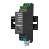
Installation Instructions
The Shelly Pro 2 smart relay (the Device) by Allterco Robotics EOOD is intended to be
mounted into a standard switchboard on DIN rail, next to the circuit breakers. Shelly
can work as a standalone device or as an accessory to a home automation
controller. Shelly Pro 2 is a two-channel relay with dry contacts and two-phase
support.
⚠CAUTION! Do not install the device at a place that is possible to get wet.
⚠CAUTION! Danger of electrocution. Mounting/ Installation of the Device to the
power grid has to be performed with caution, by a qualified electrician.
⚠CAUTION! Danger of electrocution. Every change in the connections has to be done
after ensuring there is no voltage present at the Device terminals.
⚠CAUTION! Do not connect the Device to appliances exceeding the given max load!
⚠CAUTION! Use the Device only with a power grid and appliances which comply with
all applicable regulations. A short circuit in the power grid or any appliance connected
to the Device may damage the Device.
⚠CAUTION! Connect the Device only in the way shown in these instructions. Any
other method could cause damage and/or injury.
⚠CAUTION! Тhe Device may be connected to and may control electric circuits and
appliances only if they comply with the respective standards and safety norms.
⚠RECOMMENDATION Connect the Device using solid single-core cables with
increased insulation heat resistance not less than PVC T105°C
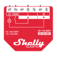
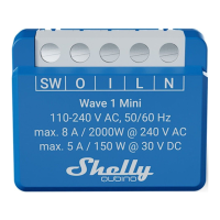
Connect the Device to the power grid and install it in the switch board as shown in
the schemes and following the Safety Instructions. Before starting
installing/mounting the Device, wire check that the breakers are turned off and there
is no voltage on their terminals. This can be done with a phase meter or multimeter.
When you are sure that there is no voltage, you can proceed to wiring the cables. If
you are using AC for the Device and the load circuits (fig.1), connect the N terminal
to the Neutral wire and the L terminal to the Device power supply circuit breaker.
Connect the two switch circuits to the S1 and S2 input terminals and the Device
power supply circuit breaker. Connect the first load circuit to the O1 terminal and the
Neutral wire. Connect the I1 terminal to the first load circuit breaker. Connect the
second load circuit to the O2 terminal and the Neutral wire. Connect the I2 terminal
to the second load circuit breaker. Two different phases can be used for the two
load circuits and a third one for the Device power supply circuit. If you are using AC
to power the Device and switch mixed DC and AC load circuits (fig.2), connect the N
terminal to the Neutral wire and the L terminal to the Device power supply circuit
breaker. Connect the two switch circuits to the S1 and S2 input terminals and the
Device power supply circuit breaker. Connect the DC load circuit to the O1 terminal
and one of the DC load circuit power supply wires. Connect the I1 terminal to the
other DCload circuit power supply wire.
⚠CAUTION The DC load circuit voltage should not exceed 30 V and the current
should not exceed 12 A.
Connect the AC load circuit to the O2 terminal and the Neutral wire. Connect the I2
terminal to the AC load circuit breaker. Two different phases can be used for the AC
load circuits and for the Device power supply circuit. If you are using AC to power the
Device and switch two DC load circuits (fig.3), connect the N terminal to the Neutral
 Loading...