EasyManua.ls Logo

Sherwood RD-6106/G/RDS User Manual

Sherwood RD-6106/G/RDS
50 pages
To Next Page IconTo Next Page
Page #1 background imageLoading...
Page #1 background image
SERVICE
MANUAL
RD-6106/G/RDS
DOLBY
DIGITAL
AC-3/DTS
READY
RECEIVER
SERERRER
te
bts
ORAL
Eohve
Lee
=
CONTENTS
«
SPECIFICATIONS
.......csescsesteseessecseesetsneeseereettnees
2
MECHANICAL
PARTS
LIST
.....cceeesssssterseeeses
23
BLOCK
DIAGRAM
.....ccccscsccstessesnsesenennerereeeteenees
9
EXPLODED
VIEW
......csescesseestesereerssreesetserreesees
24
WIRING
DIAGRAM.......ccsccsscsseseesereteeterereeseernans
10
ELECTRICAL
PARTS
LIST........cccscsssesesseetseesers
25
CIRCUIT
DESCRIPTION......ccccsccssssssseererereeeerees
11
PRINTED
CIRCUIT
BOARDS
........cssssseseeseereeees
32
ALIGNMENT
PROCEDUREG...........ccscsscserereeres
16
IC’S
FUNCTIONAL
BLOCK
DIAGRAM
............
37
TROUBLESHOOTING.
.....cceescsseeneecesenteeeeeenes
19
SCHEMATIC
DIAGRAMG.........:ccsessesssereeenerers
43
©
Sherwood.
Question and Answer IconNeed help?

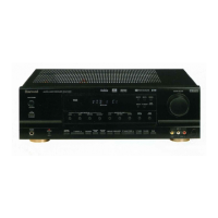
Do you have a question about the Sherwood RD-6106/G/RDS and is the answer not in the manual?

Sherwood RD-6106/G/RDS Specifications

General IconGeneral
BrandSherwood
ModelRD-6106/G/RDS
CategoryReceiver
LanguageEnglish

Summary

Safety Precautions

General Safety Precautions

Essential safety guidelines for servicing and operation of the receiver.

Receiver Specifications

Front Amp Section Specifications

Detailed performance parameters for the front amplifier stage.

Block Diagram

Overall System Block Diagram

Visual representation of the unit's main functional blocks and connections.

Wiring Diagram

PCB Interconnection Diagram

Illustrates wiring connections between different printed circuit boards.

Circuit Description

CPU Pin Description

Detailed explanation of the main CPU's pin functions.

CPU Block Diagram

Functional block diagram of the CPU and its interfaces.

CPU Pin Function Details

Further details on CPU pin functions and assignments.

Alignment Procedures

Tuner Alignment Procedures

Steps for aligning the AM and FM tuner sections.

Troubleshooting Guide

Power-Related Troubleshooting

Addresses power-on failures, fuse issues, and power interruptions.

Input and Sound Troubleshooting

Solutions for key input disorders and bump sound artifacts.

Mechanical Parts List

Cabinet and Chassis Parts

List of mechanical components for the unit's structure.

Electrical Parts List

Capacitors and Resistors

List of capacitor and resistor components used in the circuitry.

IC Functional Block Diagrams

Voltage Regulator IC Diagrams

Functional diagrams for voltage regulator integrated circuits.

Related product manuals