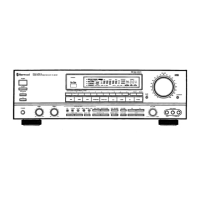
Do you have a question about the Sherwood RV-6010R and is the answer not in the manual?
Detailed performance characteristics of the amplifier circuitry.
Technical specifications for the FM tuner functionality.
Technical specifications for the AM tuner functionality.
General parameters like speaker impedance and power consumption.
Step-by-step instructions for calibrating the AM receiver circuits.
Step-by-step instructions for calibrating the FM receiver circuits.
Detailed pin configuration for the main microcomputer IC (μPD75212).
Table detailing functions assigned to each terminal of the microcomputer.
Block diagram illustrating the internal architecture of the microcomputer.
Matrix showing input/output mapping for front panel controls.
Visual layout of MAIN and SURROUND PC boards (top and bottom).
Visual layout of the FRONT PC board (top and bottom).
Visual layout of the TUNER PC board (top and bottom).
Visual layout of the BOTTOM PC board (top and bottom).
Visual layout of POWER and SELECTOR PC boards (top and bottom).
Visual layout of DRIVER, TONE, and SW PC boards (top and bottom).
Visual layout of HEADPHONE, BALANCE, LED, VOLUME, POSISTOR PC boards.
Visual layout of the REMOCON PC board (top and bottom).
Detailed list of electrical components for the main PC board.
List of ground plate and integrated circuits with part numbers.
List of resistors and diodes with part numbers.
List of connectors and diodes with part numbers.
List of capacitors, connectors, and resistors for the Front PC Board.
List of capacitors, connectors, and resistors for the Balance PC Board.
List of capacitors, connectors, ICs, and resistors for the Tone PC Board.
List of capacitors and connectors for the Posistor PC Board.
List of capacitors and connectors for the Switch PC Board.
List of capacitors and connectors for the Volume PC Board.
List of capacitors and connectors for the Bottom PC Board.
List of capacitors and connectors for the Headphone PC Board.
List of capacitors and connectors for the LED PC Board.
List of capacitors and connectors for the SW PC Board.
List of capacitors and ceramic filters for the Tuner PC Board.
List of capacitors, coils, crystals, and diodes for the Surround PC Board.
List of connectors, diodes, and ICs for the Control PC Board.
List of resistors for the FM Front End section.
List of variable resistors and transistors for the Surround PC Board.
List of capacitors, connectors, and diodes for the Surround PC Board.
List of connectors, fuses, and transformers for the Selector PC Board.
List of capacitors and connectors for the Power PC Board.
List of diodes, fuses, resistors, and transistors for the Driver PC Board.
List of mechanical components and their part numbers.
List of screws and other miscellaneous mechanical parts.
Lead identification and internal diagram for TC9176 IC712.
Diagram and pinout for the LA2730 IC710.
Diagrams and pinouts for multiple KIA4559P ICs.
Diagram and pinout for the STK 4122 II IC801.
Diagram and pinout for the LA1265 IC101.
Diagram and pinout for the BA7625 IC205.
Diagram and pinout for the HA12016 IC102.
Diagram and pinout for the M50198P IC706.
Diagram and pinout for the CTA7291S IC301.
Diagrams and pinouts for LC4966 IC704, IC705.
Diagrams and pinouts for GD7815 IC209-IC211.
Diagram and pinout for LM7001 IC103 PLL IC.
Diagrams and pinouts for LC7821 IC203, IC204.
Diagram and pinout for STK 402611 IC802.
Diagram and pinout for SSM2126 IC106.
Dual supply application diagram for SSM2126 IC106.
Diagram and pinout for GD 4011B IC1100.
Diagrams and pinouts for MC 14094B IC206, IC707, IC708.
Diagram and pinout for GD 4027B IC1101.
Schematics for different front-end versions (FE 306-A15, FE 407-G60, FE 407-A15).
| Weight | 9.5 kg (20.9 lbs) |
|---|---|
| Tuning range | FM, AM |
| Outputs | Composite, stereo audio |
| Speaker load impedance | 8 ohms |
| Video Connections | composite |
| Tuner Section | Yes |