145
(3) Gain switch condition value CDS (PB12)
As users selected "position command frequency", "position command pulse error" or motor speed"
in gain switch option (PB11), set the corresponding gain switch condition.
(*)The setting unit is as follows.
Position command frequency >= PB12
Position command pulse error >= PB12
Position command frequency < PB12
Position command pulse error < PB12
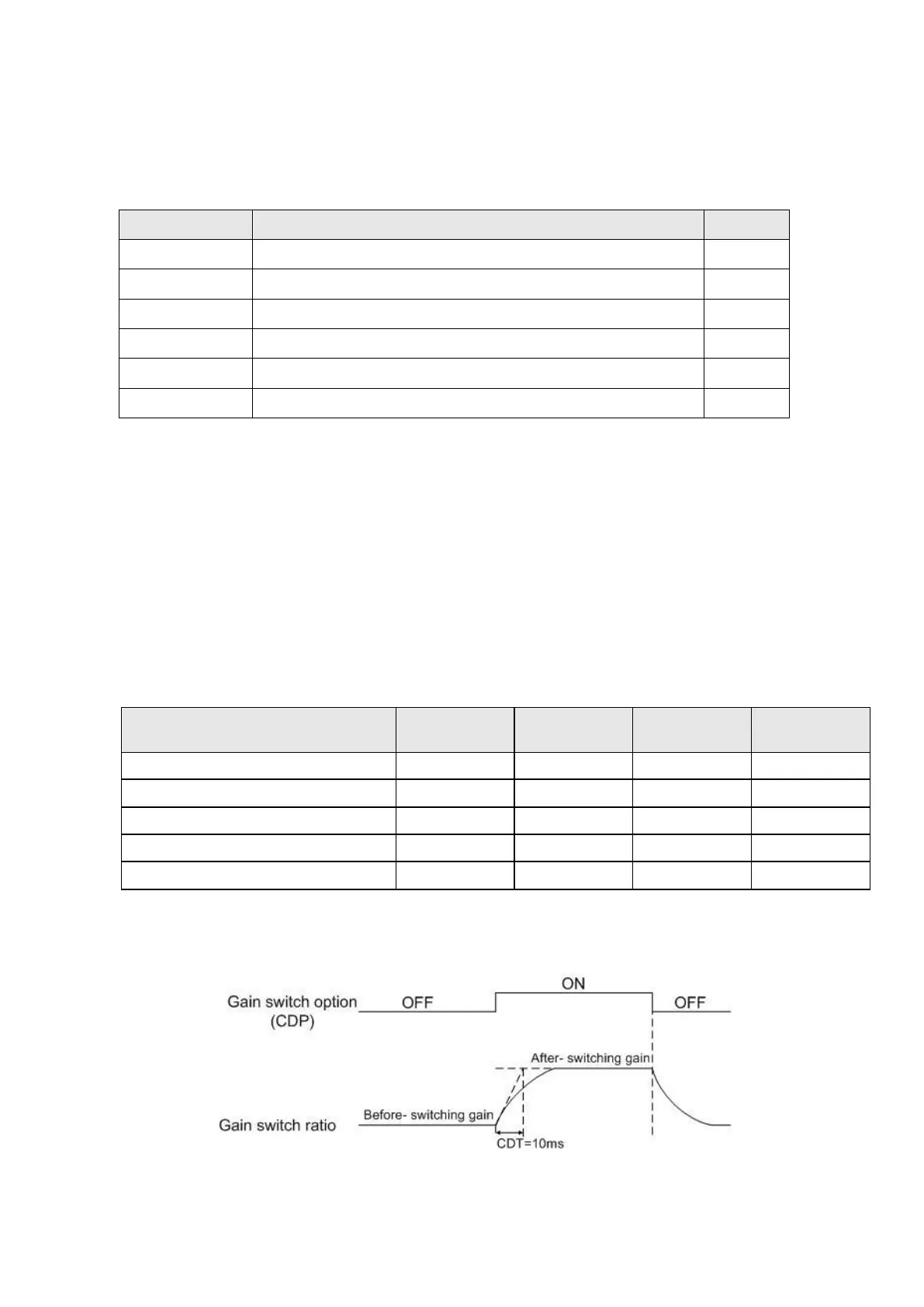
(4) Gain switch time constant, CDT (PB13)
It is used to smooth the motor running at gain switching moment to suppress vibration due to a
large gain difference.
(5) Load to motor inertia ratio 2, GD2 (PB14)
Set the demand ratio value to meet the actual load changed after switching. If the load inertia ratio
does not change, set it to the same value as GD1 (PB06).
(6) PG1, VG1, VIC
The original gain values would be switched to the ratio values of PG2/VG2/VIC2 settings.
Example 1: CDP signal is the switch trigger.
①. Relevant parameters setting: GD2=20, PG2=80%, VG2=120%, VIC2=150%
Load to motor inertia ratio
②. The sequence of gain switch
 Loading...