Heater break/loop alarm settings
Can be used if event option and CT input option is eguipped.
4-17Heater 1 break/loop alarm mode setting screen
Initial value: out1
Setting range: out1, out2
Sets control output by which heater break/loop alarm is output
by current detection by CT1.
Can be set only for control output Y or P.
4-17 – 4-22 will be displayed if output of control output 1 or 2
is Y or P, and CT input is selected at the same time.
4-18Heater 1 break alarm action value setting screen
Initial value: oFF
Setting range: oFF, 0.1 – 50.0 (A)
Sets current value of heater break alarm detected by CT1.
When control output is ON, an alarm is output if the current
value detected by CT1 is lower than the setting.
4-19Heater 1 loop break alarm action value setting screen
Initial value: oFF
Setting range: oFF, 0.1 – 50.0 (A)
Sets current value of heater loop alarm detected by CT1.
When control output is OFF, an alarm is output if the current
value detected by CT1 is higher than the setting.
4-20Heater 2 break/loop alarm mode setting screen
Initial value: out1
Setting range: out1, out2
Sets control output by which heater break/loop alarm is output
by current detection by CT2.
Can be set only for control output Y or P.
4-21Heater 2 break alarm action value setting screen
Initial value: oFF
Setting range: oFF, 0.1 – 50.0 (A)
Sets current value of heater break alarm detected by CT2.
When control output is ON, an alarm is output if the current
value detected by CT2 is lower than the setting.
4-22Heater 2 loop break alarm action value setting screen
Initial value: oFF
Setting range: oFF, 0.1 – 50.0 (A)
Sets current value of heater loop alarm detected by CT2.
When control output is OFF, an alarm is output if the current
value detected by CT2 is higher than the setting.
Analog output settings
4-23Analog output type setting screen
Initial value: PV (
)
Setting range: PV, SV (
), out1 (
),
out2 (
)
Item to be output as analog signal is set from among 4 items:
measured value (PV), target set values (SV), control output 1
(out1) and control output 2 (out2).
4-23 – 4-27 is not displayed if analogue output is not selected.
4-24Analog output scaling lower limit value setting screen
Initial value: 0.0
(For PV/SV, measureing range lower limit value;
out1/out2 is 0.0)
Setting range: When PV or SV is selected, within measuring range
When out1 or out2 is slected: 0.0 – 100.0 (%)
Minimum values of analog output signal (0mV, 4mA, 0V) are
set as scaling minimum value to be output.
4-25Analog output scaling higher limit value setting screen
Initial value: 800.0
(For PV/SV, measureing range higher limit value;
out1/out2 is 100.0)
Setting range: When PV or SV is selected, within measuring
range
When out1 or out2 is slected: 0.0 – 100.0 %
Maximum values of analog output signal (10mV, 20mA, 10V)
are set as scaling maximum value to be output.
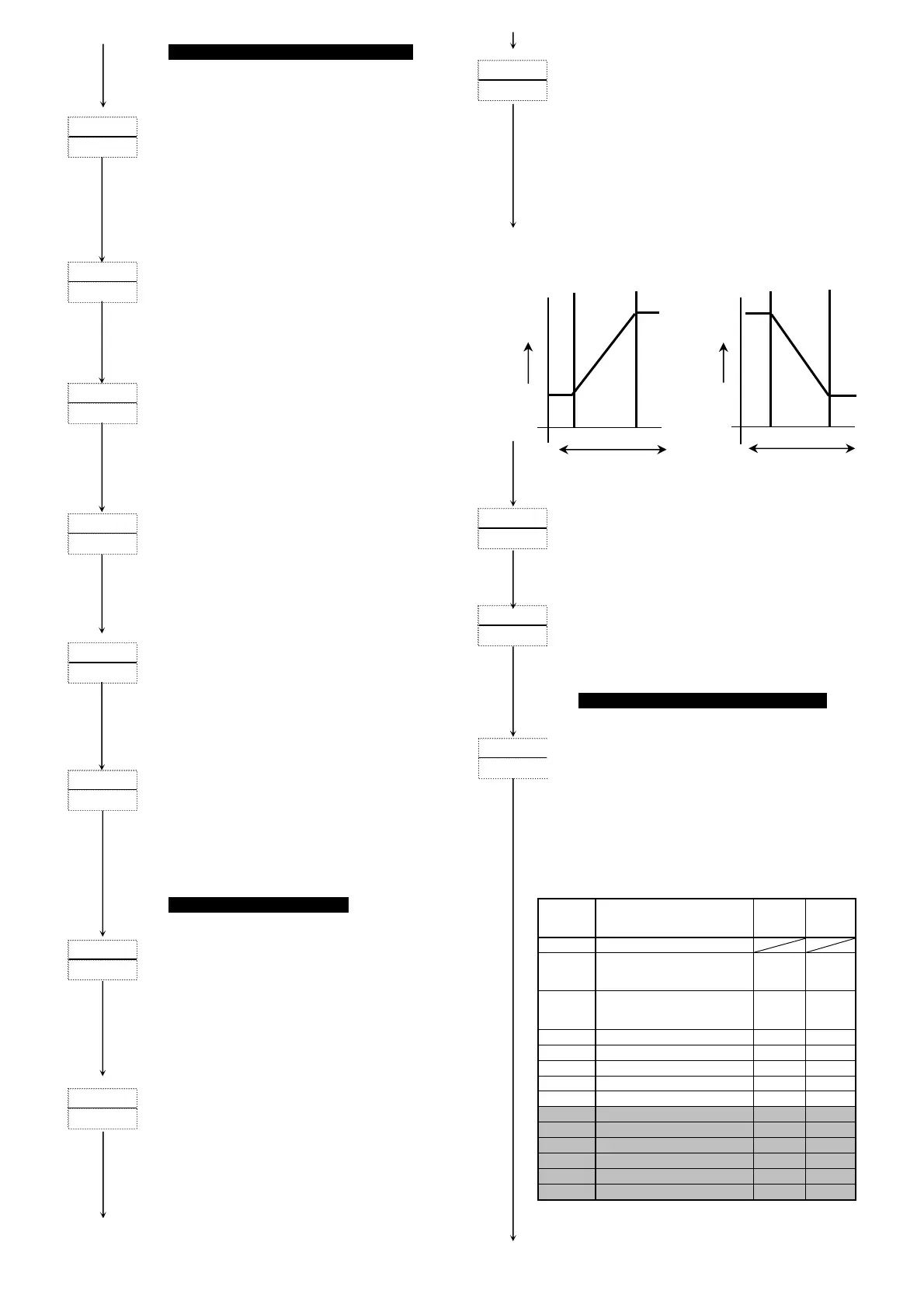
Inverse scaling is possible for Ao_L > Ao_H.
(Min. H-L=±1 count)
Characteristics by analog output scaling are as follows:
For A o_L Ao_H For Ao_L Ao_H
4-26Analog output limiter lower limit value setting screen
Initial value: 0.0 (%)
Setting range: 0.0 – 99.9 (%)
Sets lower limit value of analog output.
4-27Analog output limiter higher limit value setting screen
Initial value: 100.0 (%)
Setting range: (AL_L setting value) + 0.1 – 100.0 (%)
Sets higher limit value of analog output.
External control input DI settings
4-28DI1 mode setting screen
Initial value: non
Setting range: non, EXE1(run1), EXE2(run2), mAn, At, ESV2,
ACt1, ACt2, ProG, HLd, AdV, Ptn2, Ptn3, L_rS
Select/allocate/set according to usage objective of external
input (DI).
4-28 – 4-31 is not displayed if DI (external control input 3
points) is not selected.
DI mode allocation type code (used by 4-29, 4-30, 4-31)
Code
External control input
allocation type
Allocation
possible
DI No.
Detection
No selection
(
)
EXE/STBY (FIX fixed value
control)
RUN/RST
ro
ram control
1, 2, 3, 4
Level
(
)
EXE/STBY (FIX fixed value
control)
RUN/RST
ro
ram control
1, 2, 3, 4
Edge
MAN: Manual output 1, 2, 3, 4
Level
AT: Auto tuning execution 1, 2, 3, 4
Edge
ESV2: External selection 2bit 1, 2
Level
Output 1 output characteristics RA/DA)
1, 2, 3, 4
Level
Output 2 output characteristics RA/DA)
1, 2, 3, 4
Level
ProG: Program 1, 2, 3, 4
Level
HLd: Hold signal 1, 2, 3, 4
Level
AdV: Advance 1, 2, 3, 4
Edge
Ptn2: Start pattern selection 2bit 1, 2
Level
Ptn3: Start pattern selection 3bit 1
Level
L_rS: Total unlatching 1, 2, 3, 4
Edge
If ESV2/Ptn2 is allocated to DI1, DI2 cannot be selected.
If Ptn3 is allocated to DI1, DI2 and DI3 cannot be selected.
A single type of code cannot be allocated to more than one DI.
To 4-29 screen
To 4-25 screeen
Scaling range
0
%
Scaling range
0
%
Analog output
100
%
Analog output
100
%
0% Ao_L Ao_H 100% 0% Ao_H Ao_L 100%
 Loading...

