https://shimano-steps.com/
58 59
https://shimano-steps.com/
E6000 MANUALE8000 CONCEPT E8000 MANUAL E6000 CONCEPT
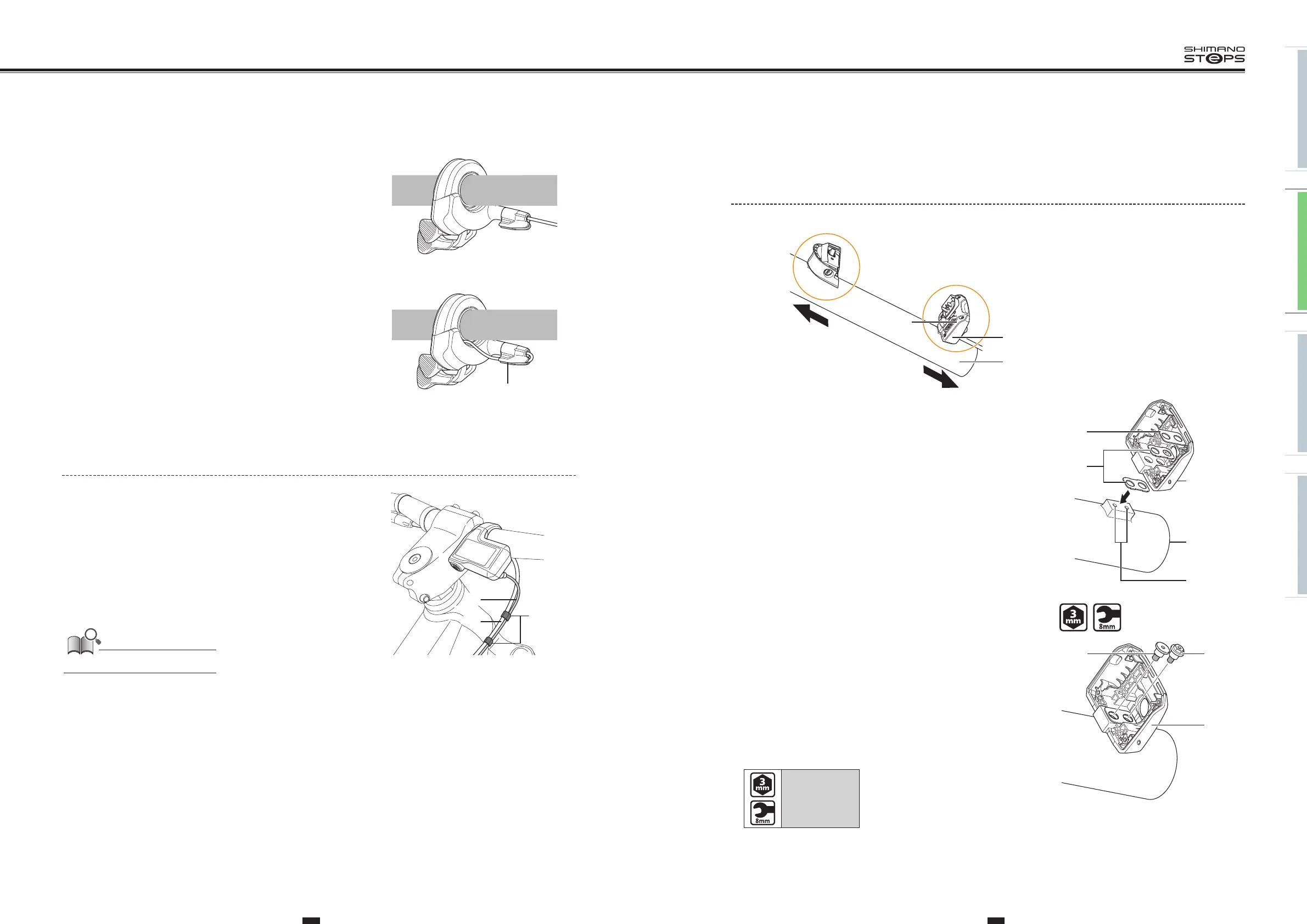
INSTALLING THE BATTERY MOUNT
BM-E8010
(A)
(B)
(E)
(y)
(z)
(D)
(C)
(y)
Front of bicycle
(z)
Rear of bicycle
(A)
Key unit
(B)
Battery connection unit
(C)
Mount upper case
(D)
Mount lower case
(E)
Frame
1. Set in place the rubber spacers and metal spacer on the mount
lower case and align the frame mounting holes with the bolt
holes in the mount lower case.
(A)
Mount lower case
(B)
Metal spacer
(C)
Rubber spacer
(D)
Frame
(E)
Frame mounting holes
(B)
(C)
(D)
(E)
(A)
2. Secure the mount lower case by tightening the two types of
mount fixing bolt (M5).
Tighten the mount fixing bolt (M5) (low head type) first.
(A)
Mount fixing bolt (M5)
(hexagon bolt type):
Use a 3mm hexagon wrench or
8mm spanner on the mount fixing
bolt.
(B)
Mount fixing bolt (M5)
(low head type):
Use a 3mm hexagon wrench on the
mount fixing bolt.
(C)
Mount lower case
Tightening torque:
3 N·m
(A)
(C)
(B)
3. Install the cable cap.
When routing the electric wire along a cable built-in handlebar,
run the wire along the guide of the cable cap then the
handlebar.
(A)
Guide
When routing the electric wire in the direction of
the stem
When using a cable built-in handlebar
(A)
Securing the electric wire (SC-E8000)
Bind the brake horse (or brake outer casing) to the electric wire
connecting the cycle computer and drive unit, using the band, as
shown in the illustration.
(A)
Electric wire of the cycle computer
(B)
Brake horse (or brake outer casing)
(C)
Band
The band is included in SC-E8000.
(A)
(B)
(C)