https://shimano-steps.com/
66 67
https://shimano-steps.com/
E6000 MANUALE8000 CONCEPT E8000 MANUAL E6000 CONCEPT
Attaching/detaching the battery on downward attachment/removal design frames
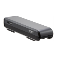
(z)
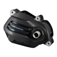
(z)
Downward attachment/
removal design frame
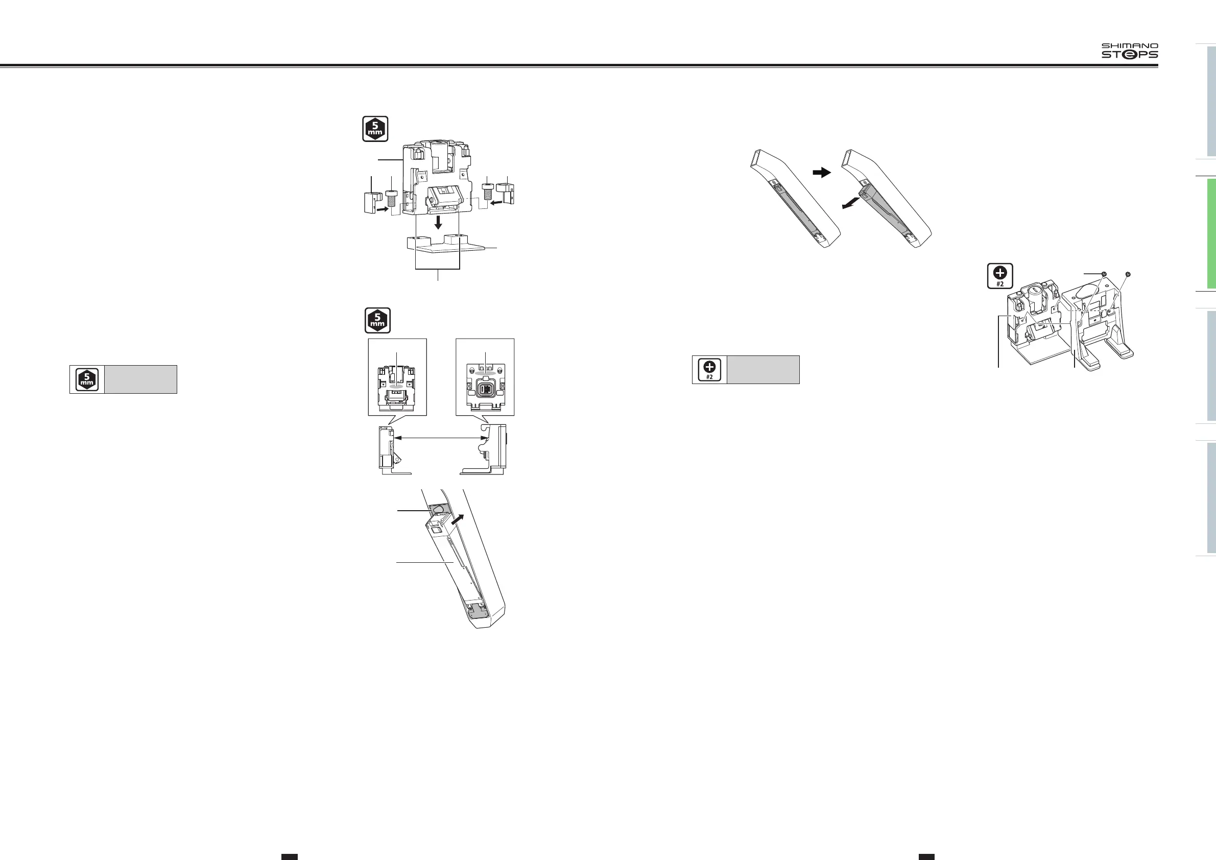
8. Attach the key unit cover to the key unit.
Secure in place the key unit with the key unit fixing bolts (M3).
(A)
Key unit cover
(B)
Key unit
(C)
Key unit cover fixing bolt (M3)
Tightening torque:
0.6 N·m
(C)
(A)(B)
5. Align the fixing bolt holes in the key unit with the frame
mounting holes.
Temporarily attach the key unit to the frame with the key unit
fixing bolts (M8).
Attach the bolt dropout prevention rubbers.
(A)
Key unit
(B)
Key unit fixing bolt (M8)
(C)
Bolt dropout prevention rubber
(D)
Frame
(E)
Frame mounting holes
(A)
(D)
(C) (B)
(E)
(B) (C)
6. Adjust the position of the key unit so that the distance between
section (A) of the key unit and section (B) of the battery
connection unit is 347.2mm and then fully tighten the key unit
fixing bolts.
Tightening torque:
10 N·m
(A)
347.2mm
(B)
7. Temporarily attach the key unit cover to the key unit and adjust
so that the battery can be smoothly connected/disconnected and
no noise is produced due to looseness during riding.
(A)
Key unit cover
(B)
Battery
(B)
(A)