https://shimano-steps.com/
70 71
https://shimano-steps.com/
E6000 MANUALE8000 CONCEPT E8000 MANUAL E6000 CONCEPT
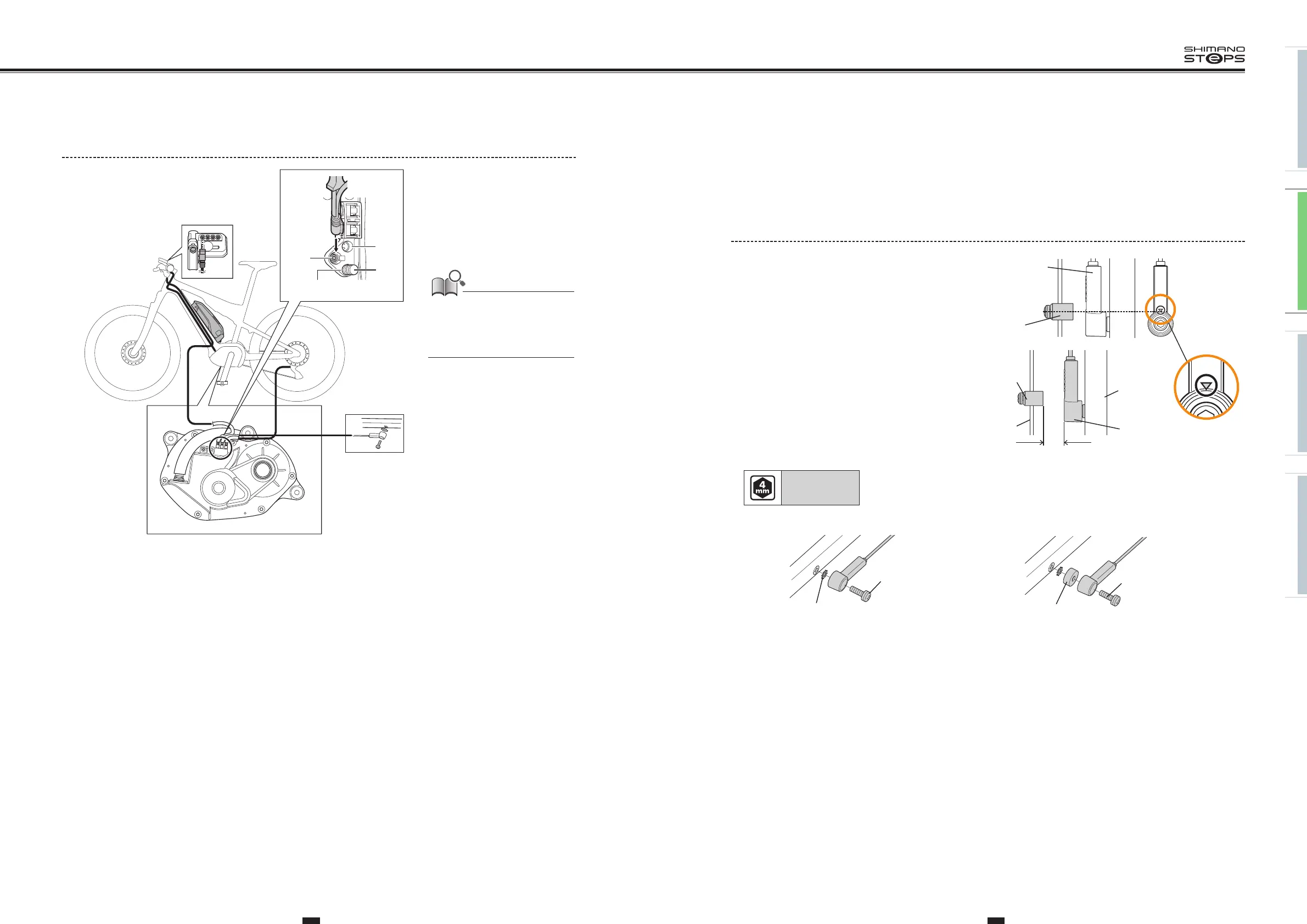
INSTALLING/REMOVING THE
SPEED SENSOR
<SM-DUE10>
1. Mounting the magnet.
Mount the magnet so that its center is aligned over the apex of
the triangle symbol.
Magnet unit
Speed sensor
Speed sensor
3-17 mm
Spoke
Chain stay
Magnet
unit
2. Before installing the speed sensor, check that
the clearance between the speed sensor and the
magnet unit will be within 3 to 17 mm.
3. Attach the speed sensor with the speed sensor fixing bolt.
Tightening torque:
1.5 to 2 N·m
•
If the clearance is within the designated range, place the
toothed washer between the speed sensor and the chain stay.
•
If the clearance exceeds
17mm
, use a spacer to adjust it.
Toothed washer
Speed sensor fixing
bolt (16 mm)
Spacer
Speed sensor fixing
bolt (22 mm)
Drive Unit Wiring Diagram
(C)
(A)
(B)
(A)
(A) Cycle computer port/
Rear derailleur port/E-TUBE
port
(B) Dummy plug
(C) Speed sensor port
• Be sure to attach dummy plugs to
any unused ports.
• The cycle computer/rear derailleur
ports can be used to connect the
cycle computer or rear derailleur.