https://shimano-steps.com/
152 153
https://shimano-steps.com/
E6000 MANUALE8000 CONCEPT E8000 MANUAL E6000 CONCEPT
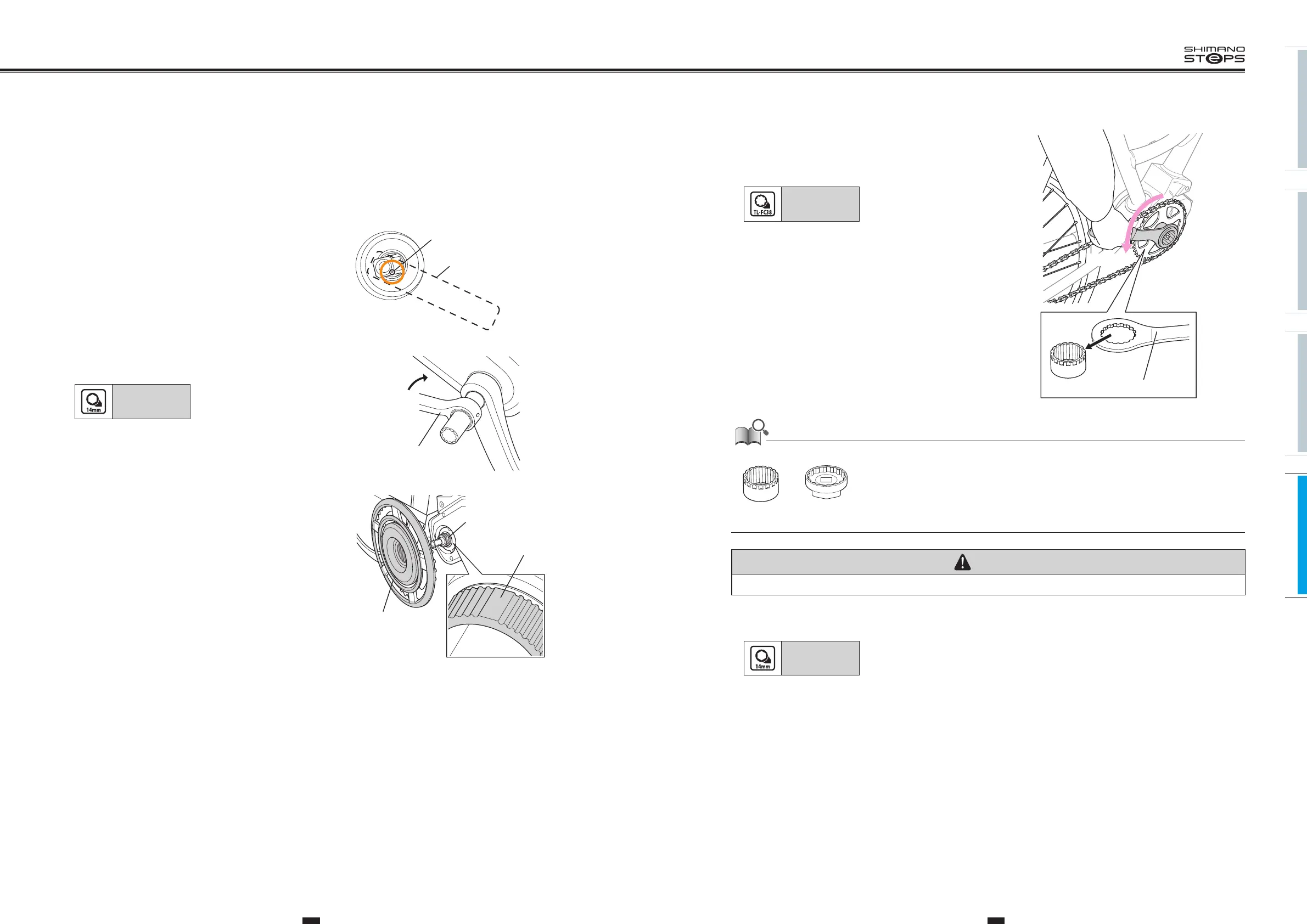
4. Tighten the lock ring by hand and attach the Shimano
original tool.
While holding the left crank, tighten the lock ring in the direction
shown in the illustration.
Tightening torque:
35 to 45 N·m
TL-FC38 TL-FC32 / FC36
Tighten
If using a torque wrench, use TL-FC38 in combination with TL-FC33.
TL-FC33TL-FC38
Note: An impact wrench cannot be used.
CAUTION
The lock ring has a left hand thread.
5. Insert the right crank arm attach the crank arm fixing bolt, and tighten it.
Tightening torque:
35 to 50 N·m
Finally, attach the crank arm cap.
6. After installing the crank arm, rotate the crank to check that it rotates smoothly.
INSTALLING THE CRANK AND
FRONT CHAINRING
Perform the procedure below for all models, regardless of whether with powered or mechanical gear shifting.
1. Install the left crank arm.
Align the round indentation on the square spindle with the
installation direction of the crank arm as shown in the illustration.
Indentation
Installation direction of
the crank arm
2. Attach the crank arm fixing bolt and tighten it with a
14 mm socket wrench.
Tightening torque:
35 to 50 N·m
14 mm
socket wrench
Tighten
3. Align the cutout in the front chainring with the wide
area on the chainring installation part when inserting
the front chainring.
For drive unit
<DU-E6000>
• When installing a front chainring labeled "SM-CRE60", a spacer
needs to be placed between the front chainring and the chainring
installation part. In this case, consult an agency.
For drive unit
<DU-E6001/E6010/E6002/E6012>
• This can be attached only on front chainrings labeled "SM-CRE60".
•
There are also models without a wide area. For those models,
positioning is not needed to install the front chainring.
Front chainring
Chainring
installation part
Wide area
 Loading...