-12-
Model D4902 (For Machines Mfd. Since 11/18)
SETUP
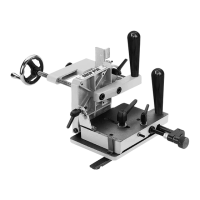
3. Loosen set screw on micro-adjust assembly, then
remove micro-adjust assembly from rod (see
Figure 7).
4. Remove (2) pre-installed M6-1 x 20 button head cap
screws that secure guide bar to base plate, then
re-install bar in inward mounting position, as shown
in Figure 7.
Figure 7. Guide bar mounted in inward
position.
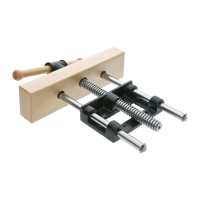
5. Thread M8-1.25 x 55 set screw removed in Step 1
back into middle, inward hole on base plate, then
tighten jam nut to secure it (see Figure 8).
6. Loosen Phillips head screw that secures pointer (see
Figure 8), and swing pointer out of the way.
7. Place slide plate onto base plate over M8-1.25 x 55
set screw, as shown in Figure 8.
Figure 8. Slide plate positioned over base
plate.
Rod
Set Screw
M8-1.25 x 55
Set Screw
Slide Plate
Pointer
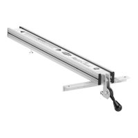
8. Slide micro-adjust collar onto rod, align micro-adjust
leadscrew with threaded guide bushing of slide
plate, then rotate knob clockwise until collar is even
with rod, as shown in Figure 9.
9. With one hand pressing slide plate flat against base
plate to properly align micro-adjust assembly, fully
tighten set screw on micro-adjust collar to secure it
to rod.
10. Re-position and secure pointer, then re-install slide
plate lock lever and flat washer.
Figure 9. Micro-adjust assembly properly
positioned.
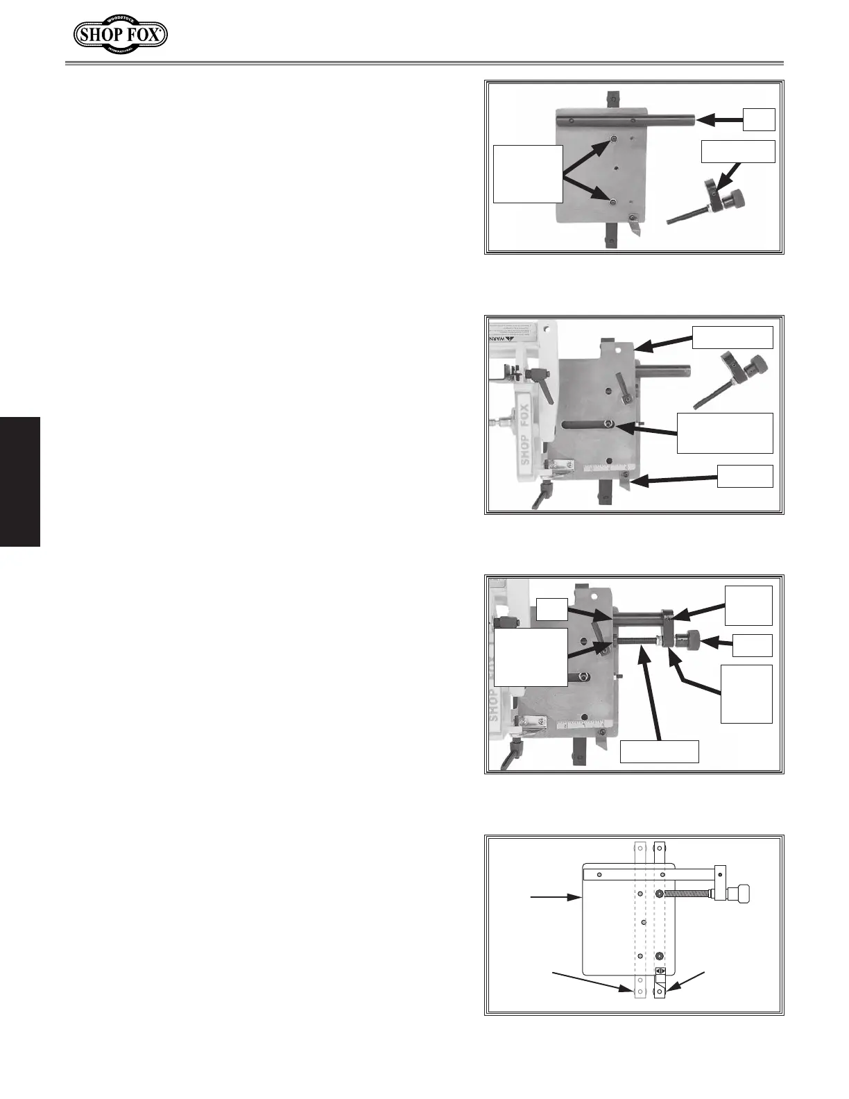
Guide Bar
Inward
Mounting
Position
Slide
Plate
Guide Bar
Outward
Mounting
Position
Figure 10. Guide bar in outward position.
To re-mount guide bar in outward position, do this
step:
1. Perform inward mounting procedure but install guide
bar using right row of mounting holes on base plate
(see Figure 10).
Inward
Mounting
Position
Rod
Knob
Threaded
Guide
Bushing
Leadscrew
Set
Screw
Micro-
Adjust
Collar
 Loading...