-17-
Model D4902 (For Machines Mfd. Since 11/18)
SETUP
7. Use micro-adjust knob to move side support against
saw blade (see Figure 16).
Note: If tenoning jig side support will not reach
the blade, you may need to re-mount guide bar
in the inward or left mounting position (refer to
Re-Mounting Guide Bar on Page 11 for detailed
instructions). If tenoning jig still does not reach the
blade after changing guide bar mounting position,
the difference can be made up when attaching
side support backing board (refer to Step 5 of
Cutting Basic Tenons beginning on Page 19 for
instructions).
— If jig side support is parallel with saw blade, no
adjustments are necessary.
— If side support and blade are not parallel, note the
difference and continue with Step 8.
Note: If side support does not quite reach the
blade, use a precise ruler to compare the distance
between the side support and the front and back of
the blade.
8. Use micro-adjust knob to align slide plate guide
bar access hole (see Figure 16) over guide bar cap
screw, then loosen cap screw.
9. Shift end of tenoning jig assembly with access hole
left or right until side support is parallel with blade,
then tighten guide bar cap screw.
10. Repeat Steps 7–9 until tenoning jig side support is
parallel with saw blade.
11. When side support is parallel with blade, use micro-
adjust knob to move side support at least
1
⁄2" away
from saw blade.
12. Tighten safety stop set screw toward slide plate lock
set screw until it just meets resistance, then tighten
jam nut to secure setting (see Figure 14). The
safety stop set screw is now correctly set to prevent
side support from contacting saw blade.
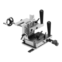
Figure 16. Side parallelism adjustment
components.
Micro-
Adjust
Knob
Guide Bar
Access Hole
Saw
Blade
Side
Support
Guide
Bar
 Loading...