Shure Incorporated
12/16
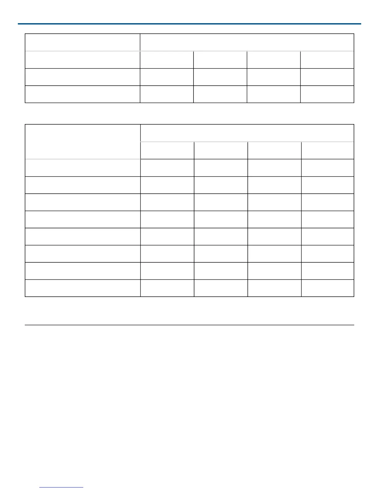
Device ID DIP Switch
5 UP DN UP DN
6 DN UP UP DN
7 UP UP UP DN
Device ID Settings
Device ID
DIP Switch
1 2 3 4
8
DN DN DN UP
9 UP DN DN UP
10 DN UP DN UP
11 UP UP DN UP
12 DN DN UP UP
13 UP DN UP UP
14 DN UP UP UP
15* UP UP UP UP
*Default setting.
Control Pin Connections
The control pins on the back of the DFR22 connect to switches, potentiometers, and controller hardware. The
Control Input pins can be used to change presets, adjust gain, and mute channels.
Use the DFR22 software to configure the control pins so that they match the attached control hardware. You can
also use the software to assign minimum and maximum gain values for each control, as well as the gain increment
for up/down volume control buttons. Refer to the Control Pin section of the Online Help or to the Online User
Guide.
Determining Control Pin Allocations
When allocating control pins, you should first determine which pins are to be used for preset control. Any remain
ing pins can then be used to adjust gain or to mute channels. The number of pins needed for preset control de
pends on the type of control hardware used, as well as the number of presets.
 Loading...