ÑÑÑÑ
1
23
4
56
7
8
9
REAR
FRONT
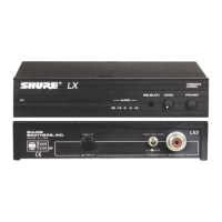
LX3 RECEIVER CONTROLS, FEATURES, & INDICATORS
FIGURE 4
1. RF Presence Indicators. Glows amber when the antenna is receiving usable RF (ra-
dio frequency) signals.
2. Audio Level Indicators. Five lights glow to indicate audio signal strength. Green
lights indicate normal operation. An amber light indicates approaching overload
condition. A red light indicates excessive audio levels.
3. Squelch Control. Sets the point at which the receiver “mutes” when the transmitter
signal becomes noisy, weak or fails. This control is factory-set at the 12 o’clock position
to provide optimal operation in most applications.
4. Audio Output Level Control. Lets you adjust output level to match the input level
requirements of a mixer or amplifier. In most situations, this control should be set
fully clockwise.
5. Power On Indicator. This green light glows to indicate that the Power switch is on
and power is applied to the receiver.
6. Power On/Off Button. Turns the receiver on and off.
7. Output Connector. Quarter-inch phone jack provides unbalanced auxiliary level
(high-impedance) output.
8. Power Jack: Accepts power from the supplied AC adapter, or from any filtered 15
to 18 Vdc (400 mA minimum) supply. It will also accept the dc power cord from a
Shure WA405 Antenna Power/Distribution System.
9. Antenna Connector. UHF-type connector provides connection to the supplied
1
/
4
-wave antenna or to coax cable used with a remote antenna. They also provide
connection to the optional Shure WA421 remote antenna cable kit used with optional
WA380 telescoping and WA490 cable-type
1
/
2
-wave antennas.

 Loading...