sync
RF Audio
OL
A B
XX YYY-ZZZ MHz Navigate
ENTER
EXIT
OFF
push
Control
POWER
Monitor
Monitor Clip
push
UR4S
Wireless Receiver
with Audio Reference Conpanding
P10T
UHF-R
Receiver
L
R
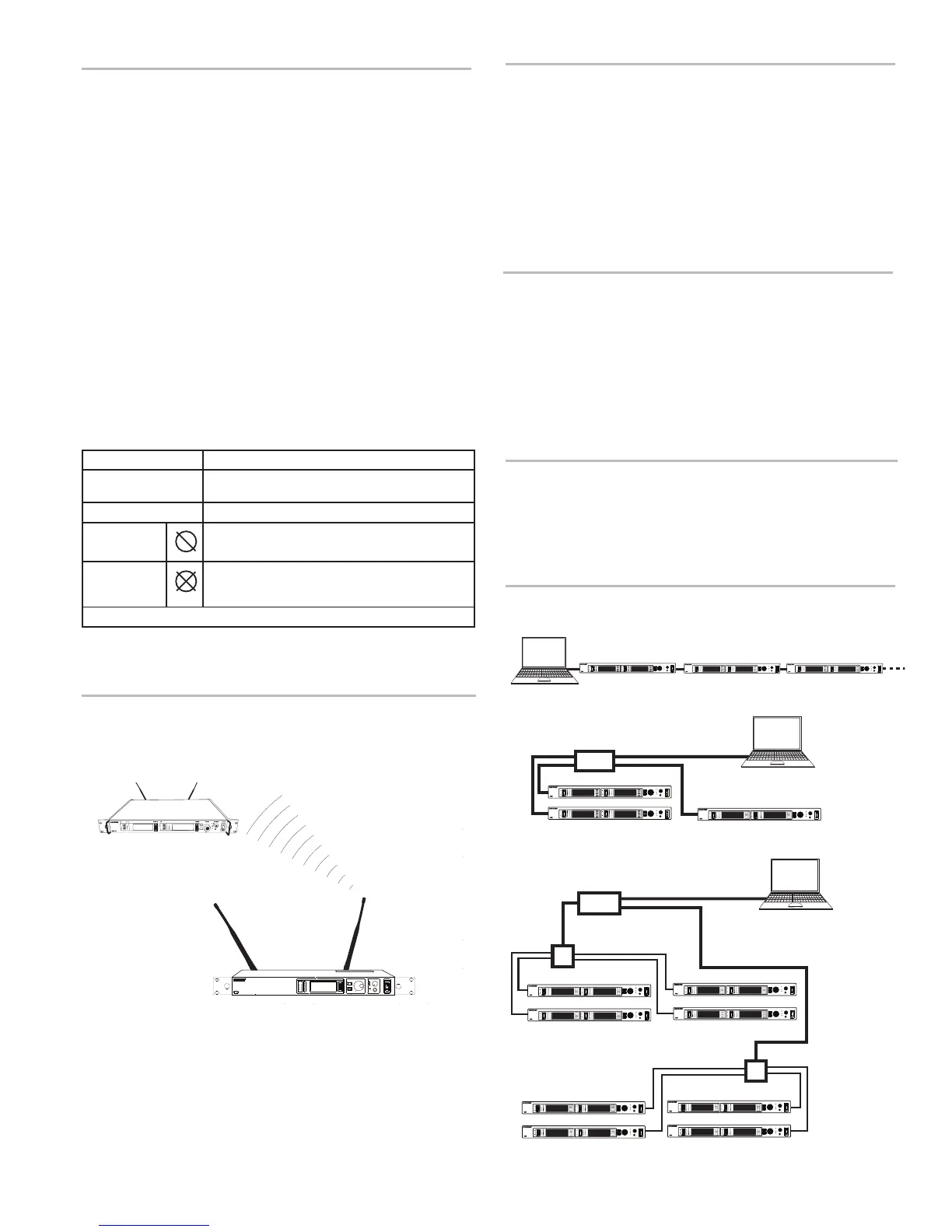
Connecting Transmitters
Router with DHCP
Computer
Extended Network
Computer
Switch
Switch
Direct
Computer
Ethernet Connection
Each transmitter has an RJ-45 port on the back for connecting to other transmitters
over an Ethernet network. Networking transmitters allows you to automatically set
frequencies for all the transmitters with a single group scan command.
Add transmitters to a network using the default automatic network setting (Util >
Network > Mode > Automatic):
1. Connect transmitters to an Ethernet router with DHCP service.
2. Use Ethernet switches to extend the network for larger installations.
3. Connect transmitters in series.
Accessing the Network with a
Computer
You can control and monitor all networked transmitters through a computer running
Shure Wireless Workbench software, Version 6 or later. If using the default auto-
matic network setting, make sure your computer is configured for DHCP.
Note: Some security software or firewall settings on your computer can prevent
you from connecting to the transmitter. If using firewall software, allow connections
on port 2201.
Static IP Addressing
Static IP addressing is also supported. An IP address can be assigned through the
network menu (Util > Network > Mode > Manual).
Note: Dual transmitters use a single IP address, which may be set through either
LCD interface.
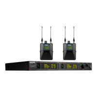
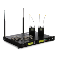
Point-to-Point Wireless Audio
Use PTP mode to allow a P10T to transmit to a UHF-R receiver. This allows a trans-
mitter and receiver setup where both units are racked and powered by AC.
For more information visit: www.shure.com/americas/products/
personal-monitor-systems
Squelch
Squelch mutes audio output from the bodypack when the RF signal become noisy.
While squelch is activated, the blue LED on the bodypack turns off.
For most installations, squelch does not need adjustment, and it keeps the per-
former from hearing hiss or noise bursts if the RF signal becomes compromised.
However, in congested RF environments or in close proximity to sources of RF in-
terference (such as large LED video panels), the squelch may need to be lowered
to prevent excessive audio dropouts. With lower squelch settings, the performer
may hear more noise or hiss, but will experience fewer audio dropouts.
Important: Before lowering squelch, first try to eliminate the problem by finding
the best set of frequencies for your installation and removing potential sources of
interference.
Caution: Turning off or lowering the squelch setting can increase the noise level
and cause discomfort to the performer:
• Do not lower the squelch setting unless absolutely necessary.
• Turn earphone volume to the lowest setting before adjusting squelch.
• Do not change the squelch setting during a performance.
• Turn up the transmitter level setting to make noise or hiss less noticeable.
Squelch Settings
HIGH (NORMAL)
Default factory setting.
MID
Moderately decreases the signal-to-noise ratio required
to squelch the receiver.
LOW
Greatly decreases the noise squelch threshold.
PILOT ONLY*
Turns off noise squelch leaving only pilot squelch on.
NO SQUELCH*
Turns off noise and pilot tone squelch. (Sometimes
used as a debugging tool by monitor engineers or RF
coordinators to "listen" to the RF environment.)
* Symbol appears in display window.
10
 Loading...