Transmitter Menu Structure and Navigation
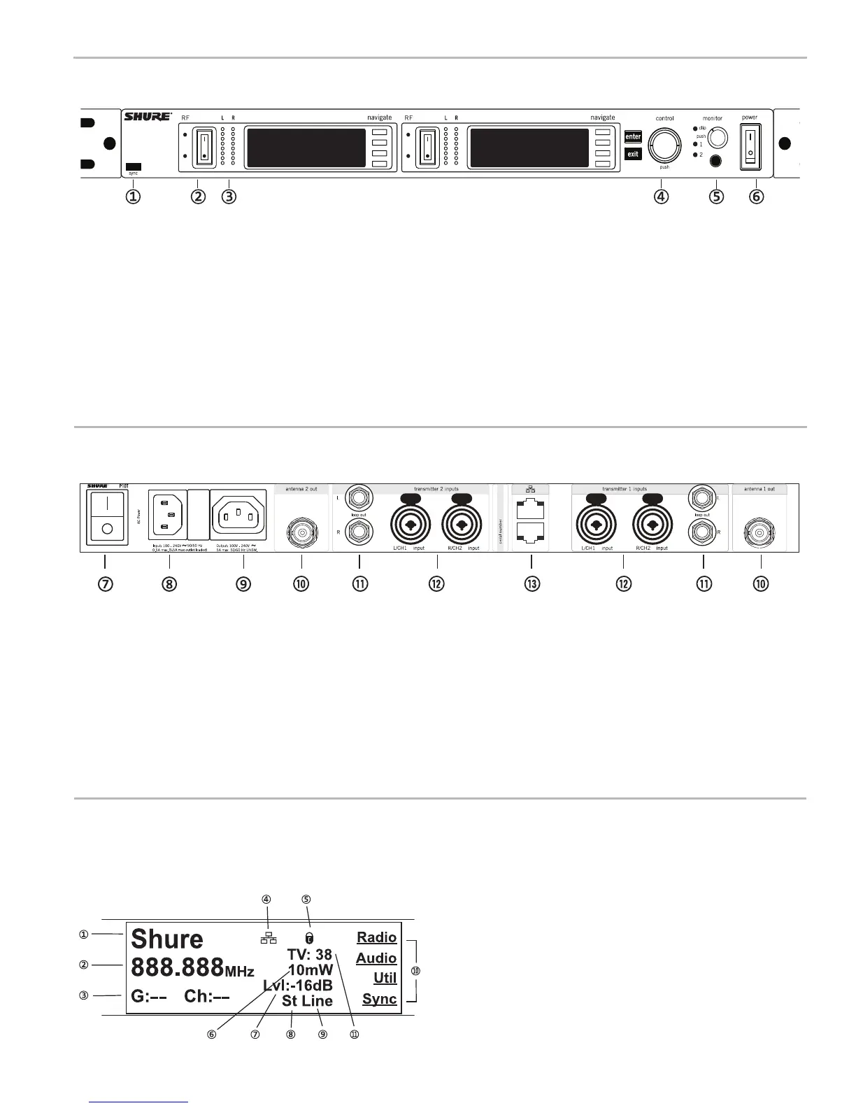
Home Screen
The home screen provides access to submenus and displays a summary of transmitter settings.
①Audiochannelname
②Frequencysetting
③GroupandChannel
④NetworkIcon
⑤LockIcon
⑥RFPowerLevel
⑦AudioLevel
⑧Mix-monoorstereo
⑨Aux/Linein
⑩Submenus
⑪TVChannel
Front Panel Controls
Rear Panel
① Sync Window
Align bodypack IR window with sync window on TX.
② RF Switch
Mutes RF output. For setting up multiple systems or adjusting settings without trans-
mitting unwanted RF or audio signals.
③ Audio Indicators
Use the control wheel to adjust the audio so that, for the average input signal level,
the top two yellow LEDs flicker and the lower LEDs are solid. Press the enter
button to save the value, exit to cancel. The red clip LED indicates the inputs are
overdriven. Reduce the level at the audio source or change the input sensitivity of
the rack unit from the Audio > Input menu.
④ Status Display and Controls
Use the navigation buttons to access the configuration menu. Push the control wheel
to move the cursor to the next item. Turn the control wheel to change a parameter—
the enter button flashes. Press it to save the value. Press the exit button to cancel
changes and return to the previous menu.
⑤ Headphone Monitoring
The monitor control adjusts signal output to the 3.5 mm headphone jack. Push but-
ton to toggle between transmitters. Monitor clip LED indicates headphone audio is
clipping.
⑥ Power Switch
Turns the unit on and off.
⑦ Primary power switch
This switch disconnects power to the unit. It is not affected by the interface power
lock in the Util menu. Only the front power switch can be locked.
⑧ Power plug
AC mains power input, IEC Connector 100-240 Vac.
⑨ AC mains power passthrough
Use with an IEC extension cable to supply AC power to another device. Unswitched.
⑩ Antenna (BNC) port
Attach supplied antennas. If you are rack mounting, use a front panel or remote
mounting kit from Shure.
⑪ loop out
Sends audio signal going into the transmitter to another device.
⑫ Audio Inputs
Connect to balanced or unbalanced outputs. Use either jack for mono input. Accepts
male XLR or 6.35 mm (1/4-inch) TRS plugs.
⑬ Ethernet Jack
Two-port RJ-45 Ethernet jack for connection to a network or computer.
4
 Loading...