CONNECTIONS
CAUTION: Do not solder terminal leads or terminal jacks to cartridge
terminals. If cartridge shell leads do not have terminal jacks, solder
jacks provided to existing colored wire leads, and slip the jacks over
the cartridge terminals. Soldering should not be done while jacks are
on cartridge terminals.
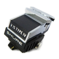
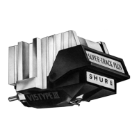
The Shure
V-15
Type Ill Cartridge utilizes a 4-terminal arrangement
for connections having a separate ground terminal for each channel.
(See illustration).
For Stereo reproduction terminal
"R"
and its ground terminal
"RC"
represent the right channel (outside groove wall). Terminal "L" and
its ground terminal
"LC" represent the left channel (inside groove
wall).
4-Lead Stereo Connection: To use a 4-lead arrangement, connect the
"hot" lead of the right channel to terminal
"R"
and the shield or
ground lead of the right channel to terminal
"RG."
Connect the
"hot" lead of the left channel to terminal
"L"
and the shield or
ground lead of the left channel to
"LC." To prevent "ground loops"
and hum, no common ground connection should be used at the
cartridge terminals. In many tone arms, the wiring is color coded to
match the color coded rings on the cartridge terminal pins.
 Loading...