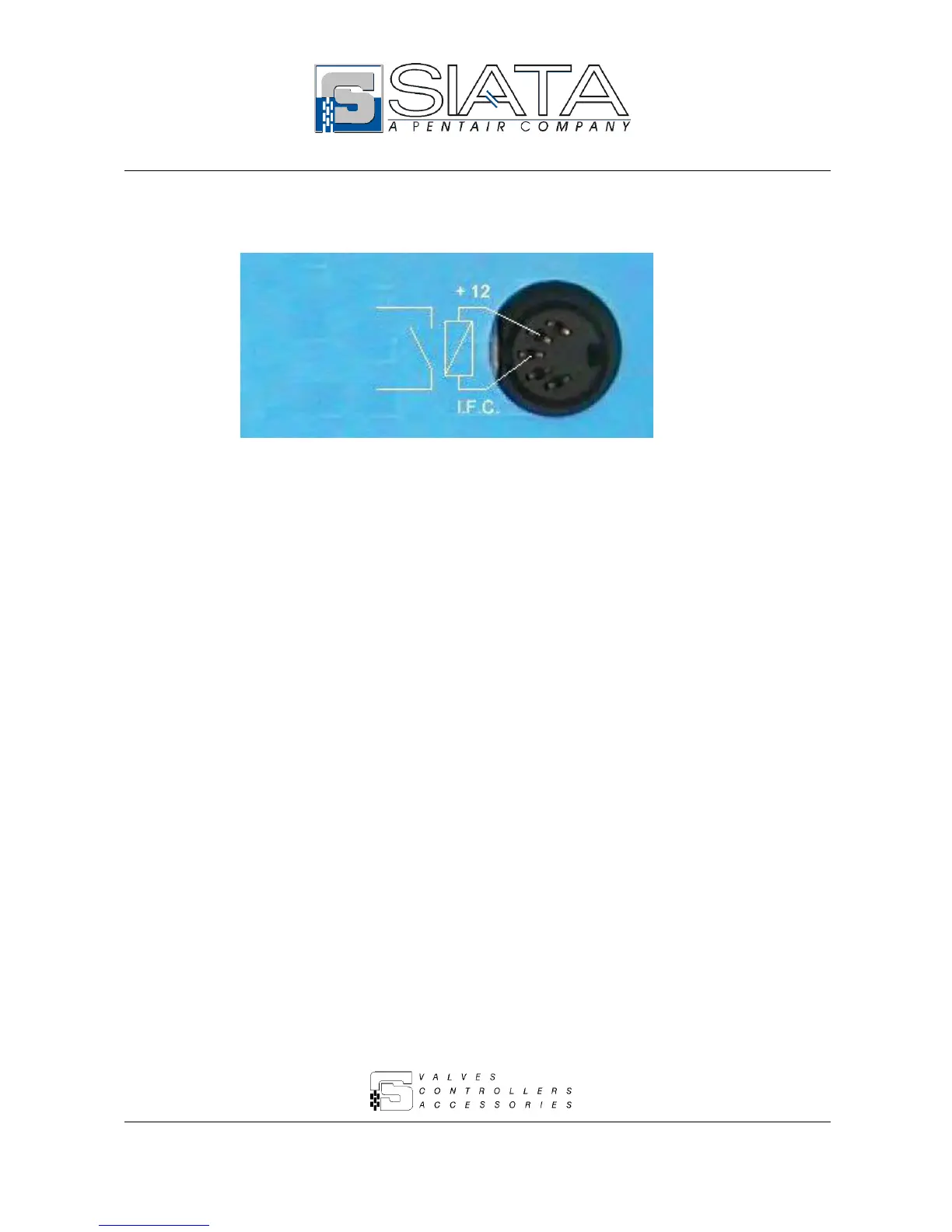
EasyManuals Logo

SIATA AQUA IONIC User Manual

SIATA AQUA IONIC
24 pages
To Next Page IconTo Next Page
To Previous Page IconTo Previous Page
Page #17 background imageLoading...
Page #17 background image
Aqua Ionic - 17 di 24
6.8 – Connections
Fig. 6 shows the correct usage of the signals issued by Aqua Ionic in the Open Collector mode. The
relay indicated in the figure must be connected between the terminal of the +12 Vdc and the
terminal of the signal concerned (in the example it is the cycle-end impulse).
Please refer to the table of par. 6.8.1 to learn which signals are issued by the controller in the Open
Collector mode.
The maximum relay absorbency for the trip coil excitation must be 20mA.
Here below follow the codes of a few relays that can be used to this purpose, all of them with a trip
coil to be supplied with 12 Vcd.
Manufacturer
Model
OMRON
G5V-1 12Vdc
TAKAMISAWA
MZ-12HS-U
MATSUSHITA
JQ1-12V or JQ1a-12V or HD1-M-DC12V
Fig. 6

Questions and Answers:

Question and Answer IconNeed help?

Do you have a question about the SIATA AQUA IONIC and is the answer not in the manual?

SIATA AQUA IONIC Specifications

General IconGeneral
BrandSIATA
ModelAQUA IONIC
CategoryController
LanguageEnglish

Related product manuals