EasyManuals Logo

SIATA AQUA IONIC User Manual

SIATA AQUA IONIC
24 pages
To Next Page IconTo Next Page
To Previous Page IconTo Previous Page
Page #18 background imageLoading...
Page #18 background image
Aqua Ionic - 18 di 24
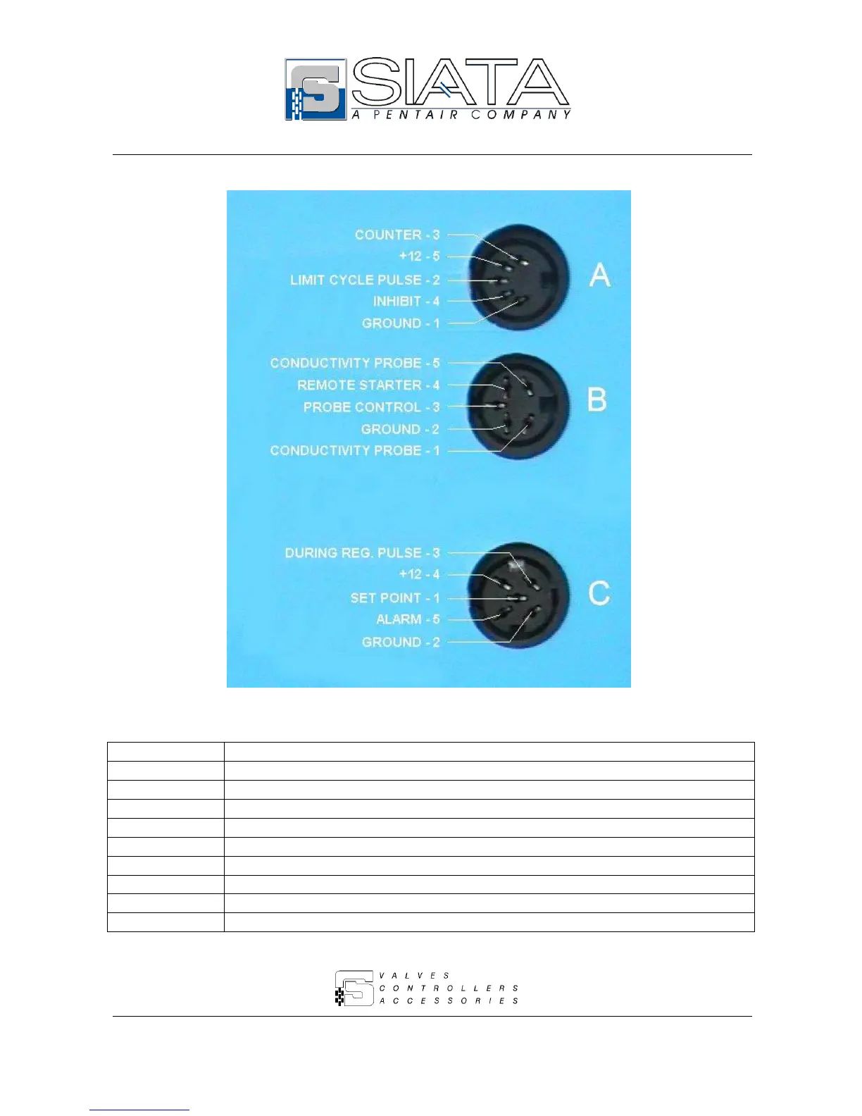
6.8.1 – Connection of this version to 3 DIN sockets
Fig. 7 shows the connections of the 3 DIN sockets, to be used as follows:
Contacts
Function
DIN A, 1 – 3
Volume, Reed counter or with make, not supplied.
DIN A, 1 – 3 – 5
Volume, Hall effect magnetic counter supplied by a +12 Vdc voltage.
DIN A, 1 – 4
Inhibition signal input (when closed).
DIN A, 2 – 5
Output of the Cycle End Impulse in the Open Collector mode.
DIN B, 4 – 2
Input of the Remote start signal (when closed).
DIN B, 3 – 2
Input of the regeneration quality control activation signal.
DIN C, 1 – 4
Output of the Set Point signal in the Open Collector mode.
DIN C, 3 – 4
Output of the Impulse During Regeneration signal in the Open Collector mode.
DIN C, 5 – 4
Output of the Alarm signal in the Open Collector mode.
Fig. 7

Questions and Answers:

Question and Answer IconNeed help?

Do you have a question about the SIATA AQUA IONIC and is the answer not in the manual?

SIATA AQUA IONIC Specifications

General IconGeneral
BrandSIATA
ModelAQUA IONIC
CategoryController
LanguageEnglish

Related product manuals