106 Operator's Manual S 65 E - S 65 E C
To choose the exact position of weight P2 in relation to the unbalance Pe, use the 6
o'clock point as your reference if “LASER” configuration is active, or the 12 o'clock point
if the “H12” or “CLIP” configuration is active.
TheanglebetweenP1andP2mustbelessthan120°andmustincludetheouterweight
Pe.
8.Iftheangleselectedisgreaterthan120°,themachinedisplaysFig.18aforapprox.3
seconds to indicate that the procedure in step 7 must be repeated correctly. If the angle
selectedislessthan120°,themachineimmediatelydisplaysthevalueofthetwoouter
weights P1 and P2 on the screen.
9. Move the wheel to a centred position (P1 or P2).
10. The brake intervenes automatically in the centred position, then apply the balancing
weight indicated on the monitor as described in the chapter “ALU 1P, ALU 2P programmes”.
11. Move the wheel to a centred position (P1 or P2).
12. Repeat the operations in step 10.
13. Once the Hidden Weights programme procedure is complete, you may continue
working with any other balancing programme.
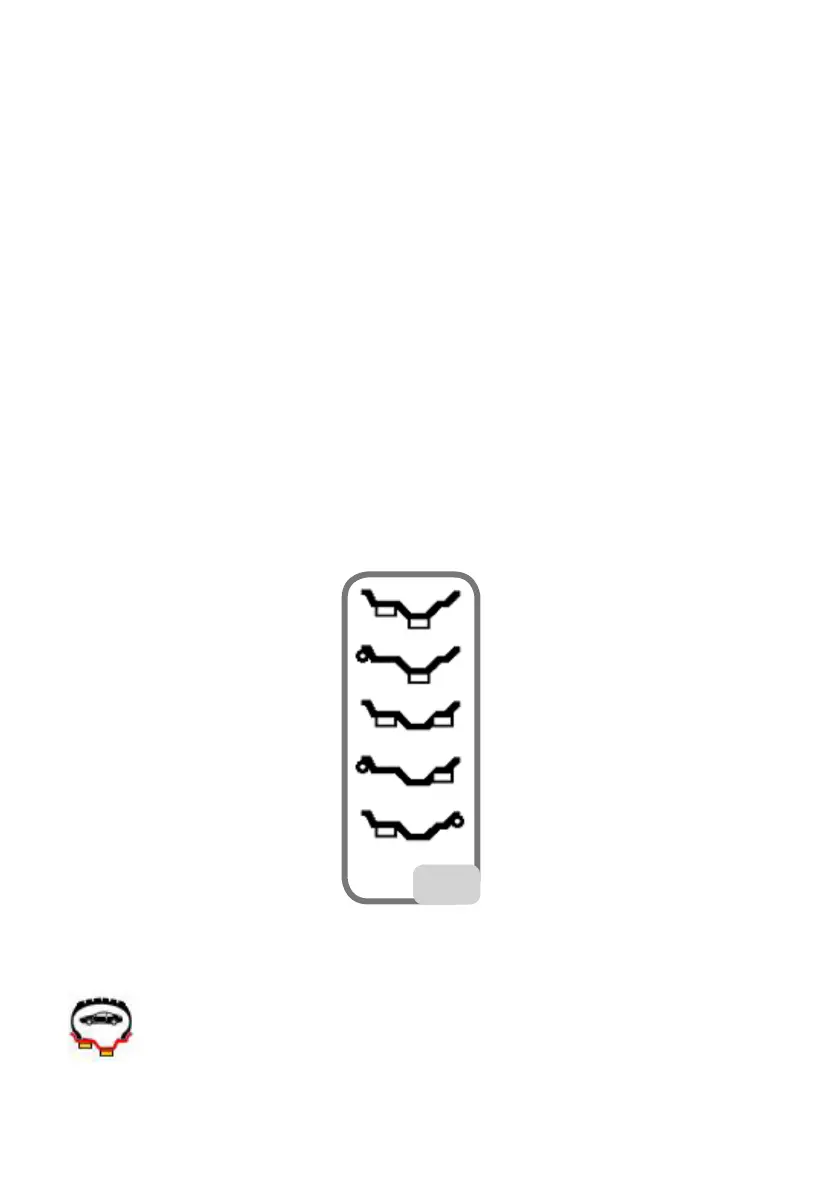
Standard ALU Programmes
(ALU 1, 2, 3, 4, 5)
Standard ALU programmes take into account the different possibilities of weight ap-
plication (fig. 23)
23
and provide correct unbalance values while maintaining the rated geometric data set-
ting of the alloy wheel.
ALU 1 balancing programme:
calculates statistically the balancing weights to be applied on the inner part of the rim,