Operator's Manual S 65 E - S 65 E C 93
14b
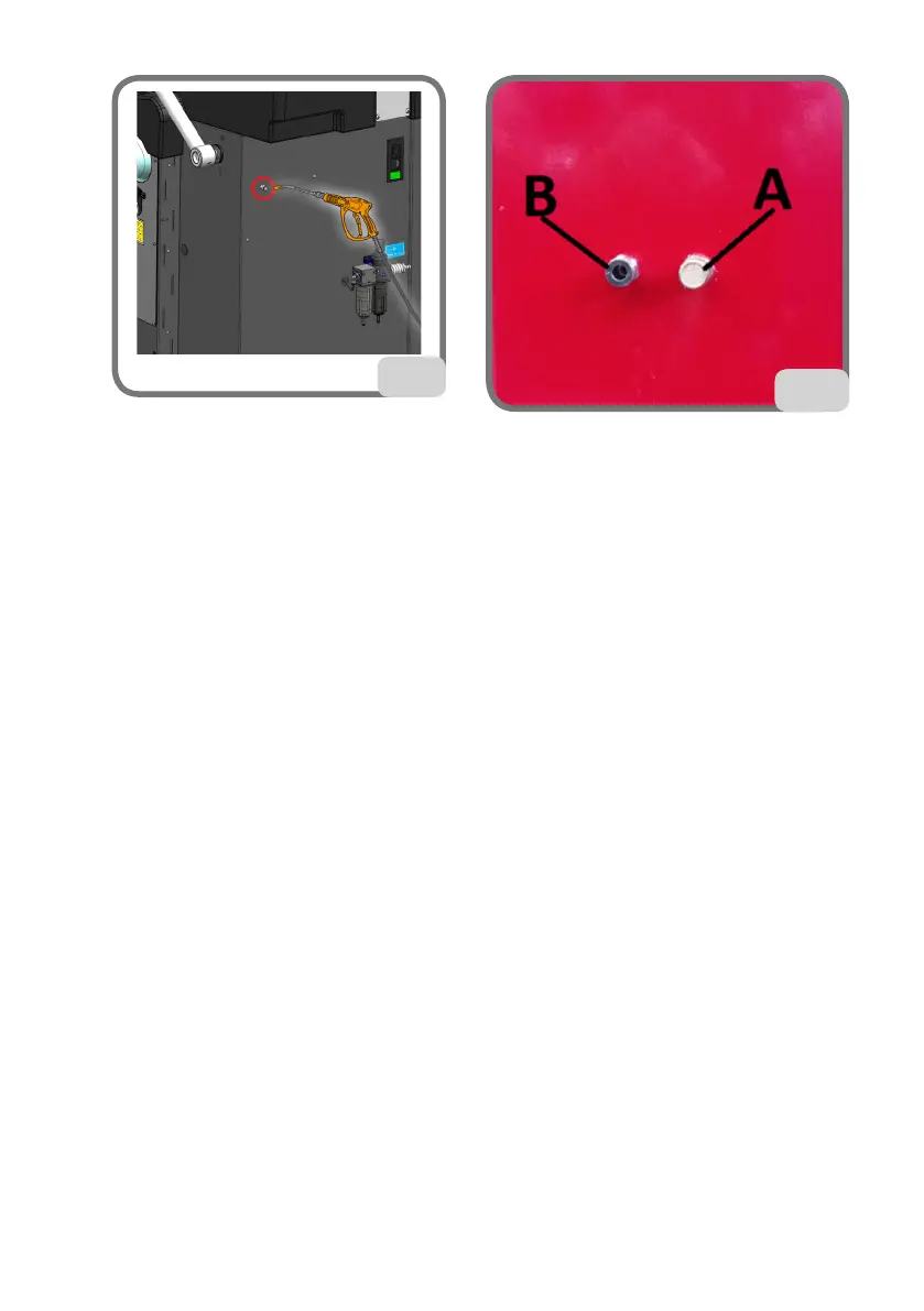
In machines where the adjustable discharge A of figure 14c is also present on the rear
side of the body, it is possible to remove the wheel possibly present on the machine by
proceeding as follows:
- Close the adjustable drain A (fig. 14c);
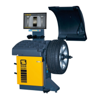
- Blow compressed air on the fitting B in the figure 14c;
- restore the correct functioning of the wheel locking device by returning the adjustable
outlet A in the above conditions to closing.
14c