FLOWSIC600 DRU
FLOWSIC600 · Addendum to Operating Instructions · 8017812/ZYM6/V1-6/2018-05 · © SICK Engineering GmbH 11
2.3
Installation
2.3.1 Mechanical Installation
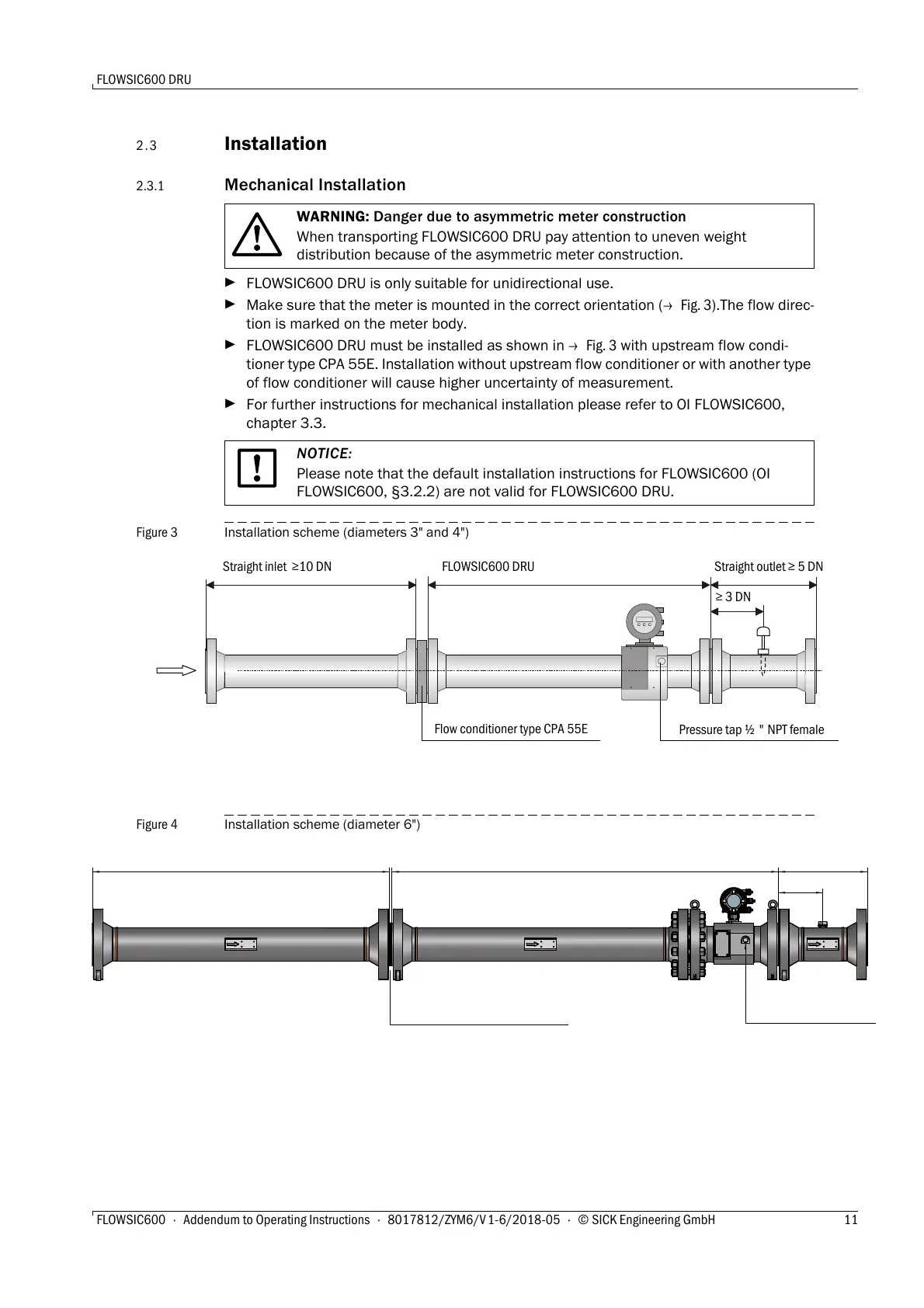
FLOWSIC600 DRU is only suitable for unidirectional use.
Make sure that the meter is mounted in the correct orientation (
Fig. 3).The flow direc-
tion is marked on the meter body.
FLOWSIC600 DRU must be installed as shown in
Fig. 3 with upstream flow condi-
tioner type CPA 55E. Installation without upstream flow conditioner or with another type
of flow conditioner will cause higher uncertainty of measurement.
For further instructions for mechanical installation please refer to OI FLOWSIC600,
chapter 3.3.
Figure 3 Installation scheme (diameters 3" and 4")
Figure 4 Installation scheme (diameter 6")
WARNING: Danger due to asymmetric meter construction
When transporting FLOWSIC600 DRU pay attention to uneven weight
distribution because of the asymmetric meter construction.
NOTICE:
Please note that the default installation instructions for FLOWSIC600 (OI
FLOWSIC600, §3.2.2) are not valid for FLOWSIC600 DRU.
≥ 3 DN
Straight inlet ≥10 DN FLOWSIC600 DRU Straight outlet ≥ 5 DN
Flow conditioner type CPA 55E
Pressure tap ½ " NPT female
≥ 3 DN
Straight inlet ≥10 DN FLOWSIC600 DRU
Straight outlet ≥ 5 DN
Flow conditioner type CPA 55E
Pressure tap ½ " NPT female

 Loading...


