3 Mounting
WARNING
Mount
ing is only allowed to be performed by qualified safety personnel.
Observe EN ISO 14119 for using interlocking devices associated with physical guards.
►
F
it the rope pull switch such that
°
the machine is reliably shut down on actuation of the rope in all directions
and the blue reset lever engages in the OFF position “0”,
°
the rope extends along the entire operating area and can be accessed easily
and safely,
°
the entire length of the rope can be seen on the actuation of the blue reset
lever.
WARNING
On lon
g sections or if the rope changes direction around a corner, it is recommended to
install 1 switch at each end of the rope.
The use of a rope pull switch in combination with a tensioning spring or two rope
pull switches is only permitted up to a certain cable length (see figure 2). Whether a
tensioning spring can be used depends on the risk assessment. The risk assessment
must take into consideration the possibility of an unplanned jamming of the tensioned
rope over its entire length!
►
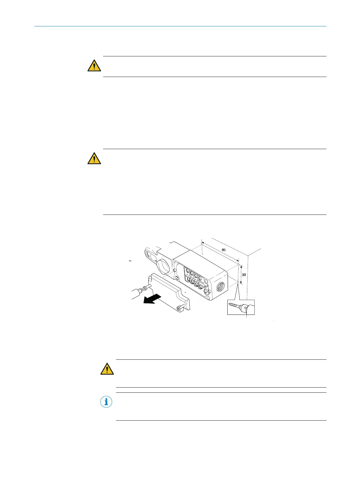
Mount t
he rope-operated switch using 4 M5 screws.
Figure 1: Installing the switch
►
Tighten screws to 5.0 Nm.
►
Install actuation rope.
Max. rope length: 10 … 30m
WARNING
F
or rope lengths of 10m to 30m, a rope pull switch must be used at both ends of
the rope.
NOTE
F
or rope lengths up to 10 m the SICK tensioning spring (part no. 5311290) can be
used instead of the second rope switch.
°
T
he first and last eye bolt must both be fastened 125 mm from the rope
switch or from the tensioning spring. All further eye bolts are placed 2 to 3 m
apart.
°
The tensioning roller is fitted in the middle of the rope.
MOUNTING 3
8027296/1KR8/2023-07-31 | SICK O P E R A T I N G I N S T R U C T I O N S | i110RP
7
Subject to change without notice