4 Electrical installation
WARNING
T
he electrical connection is only allowed to be made by qualified safety personnel.
4.1 Variants with M20 cable entry
►
F
it cable gland M20 with the corresponding enclosure rating.
►
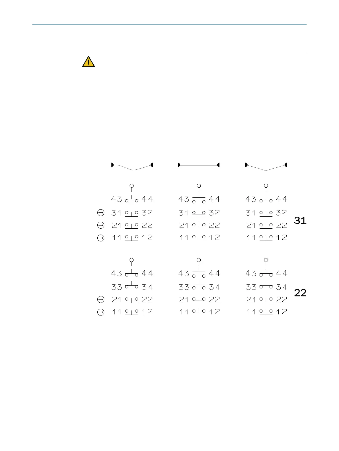
Contact assignments see figure 5, page 9.
►
Operate all contact pairs in the same voltage range.
►
Connect all live parts to one side of the contact block.
►
The PE connection must be made using a cable lug.
Rope
slack
Rope
tensioned
actuated
Figure 5: Switching elements and switching functions
►
T
ighten the clamping bolts to 1.0Nm.
►
Ensure the cable entry is leak-proof.
►
Close and screw switch cover in place.
►
Tighten screws to 2.0Nm.
ELECTRICAL INSTALLATION 4
8027296/1KR8/2023-07-31 | SICK O P E R A T I N G I N S T R U C T I O N S | i110RP
9
Subject to change without notice