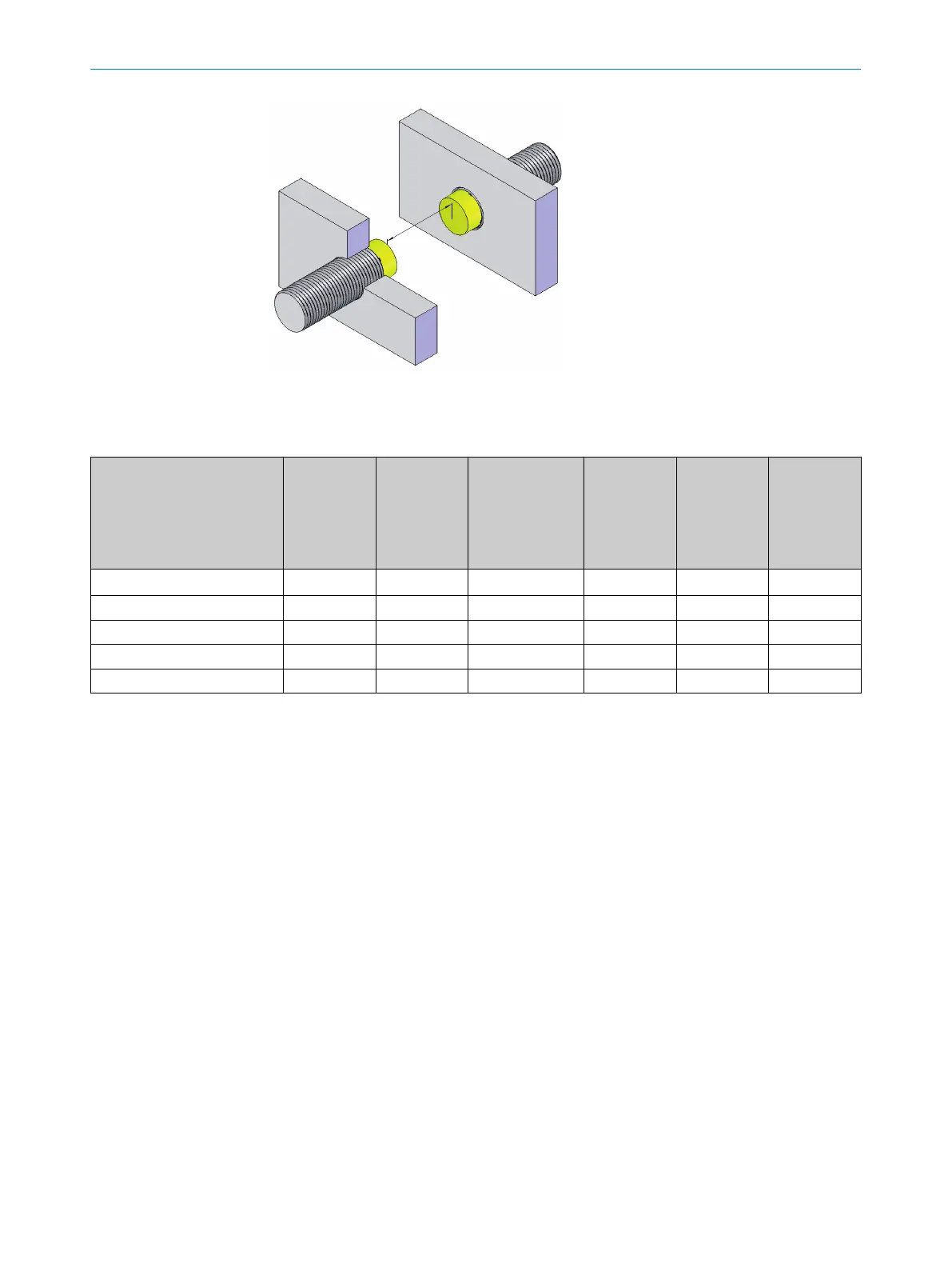
Figure 6: Distance for 2 opposing safety
switches
Table 5: Dimensions for non-flush mounting in mm
Variant
1
Diame
ter of
the safety
switch
2
Minimum
distance to
the neighbor‐
ing safety
switch
3
Minimum free
space above the
active sensor
surface
4
Minimum
free space
around the
active sensor
surface
5
Overrun of
the active
sensor sur‐
face
6
Minimum
distance to
the opposing
safety switch
General formula –
> 2 × 1
> 3 × S
n
> 1 × 1
> 2 × S
n
> 8 × S
n
IME2S12-04***** 12 > 24 > 12 > 12 > 8 > 32
IME2S12-08***** 12 > 24 > 24 > 12 > 16 > 64
IME2S18-08***** 18 > 36 > 24 > 18 > 16 > 64
IME2S30-15***** 30 > 60 > 45 > 30 > 30 > 120
MOUNTING 5
8023341/14TD/2019-08-08 | SICK O P E R A T I N G I N S T R U C T I O N S | IME2S
17
Subject to change without notice