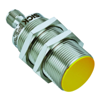
Figure 8: No potential difference between load and protective device
6.2 Notes on cULus
Important information
DANGER
Ris
k of burns from hot housing
b
Take measures to make sure the safety switch cannot be touched during opera‐
tion.
For use according to the requirements of UL 60947-5-2, the following conditions must
also be me
t:
•
The voltage supply must correspond to Class 2 in accordance with UL 508
•
Voltage supply U
v
secured with 1 A fuse
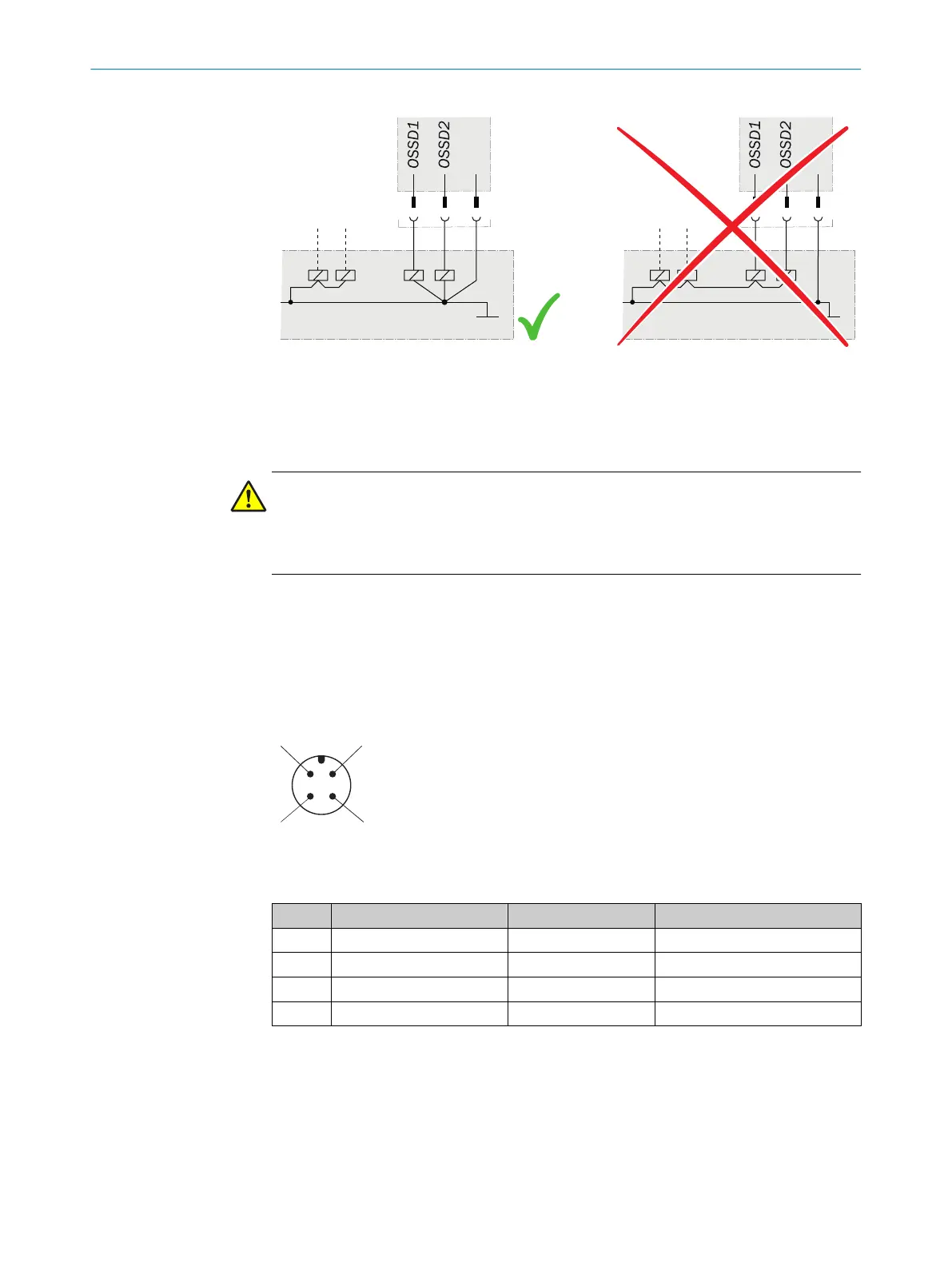
6.3 System connection (M12, 4-pin)
Figure 9: System connection pin assignment (male connector)
Table 6: Device connection pin assignment (male connector, M12, 4-pin, A-coded)
Pin Wire color
1)
Designation Description
1 Brown +24 V DC Voltage supply 24 V DC
2 White OSSD 1 Output OSSD1
3 Blue 0 V Voltage supply 0 V DC
4 Black OSSD 2 Output OSSD2
1)
Applies to the extension cables recommended as accessories.
b
P
ay attention to seal tightness of the plug connector.
ELECTRICAL INSTALLATION 6
8023341/14TD/2019-08-08 | SICK O P E R A T I N G I N S T R U C T I O N S | IME2S
19
Subject to change without notice