Table 4: Dimensions for flush mounting in mm
Variant
1
Diame
ter of the safety switch
2
Minimum dis‐
tance to the
neighboring
safety switch
3
Minimum free
space above the
active sensor
surface
6
Minimum dis‐
tance to the
opposing safety
switch
IME2S12-04***** 12 > 24 > 12 > 32
IME2S18-05***** 18 > 36 > 15 > 40
IME2S18-08***** 18 > 36 > 24 > 64
IME2S30-12***** 30 > 60 > 36 > 96
General formula –
2 × 1
> 3 × S
n
> 8 × S
n
5.2 Non-flush mounting
Important information
DANGER
If t
he safety switch is not mounted with the intended mounting method, the switching
behavior is affected. The safety switch might not switch as intended.
b
Only use safety switches for flush mounting which are intended for flush mounting.
b
Only use safety switches for non-flush mounting which are intended for non-flush
mounting.
b
If something is unclear, use the part number to check for which mounting method
the safety switch is suited (see "Ordering information", page 32).
Approach
b
F
or mounting, observe max. tightening torque: 12 Nm
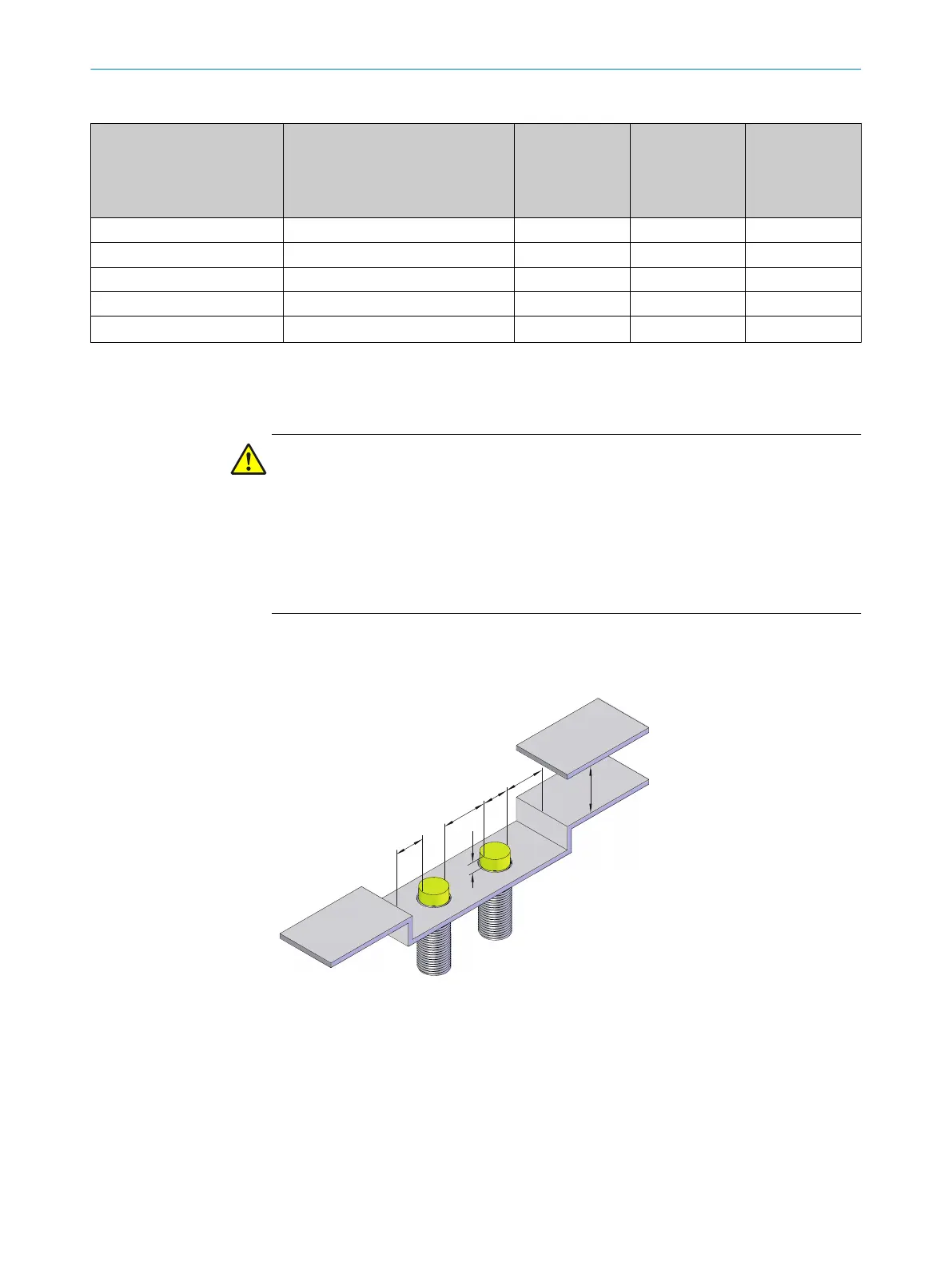
Figure 5: Distances for non-flush mounting
5 MOUNTING
16
O P E R A T I N G I N S T R U C T I O N S | IME2S 8023341/14TD/2019-08-08 | SICK
Subject to change without notice