a: f = 9.6 mm
b: f = 17.1 mm
0
200 x 160
400 x 320
600 x 480
800 x 640
1000 x 800
1200 x 960
0 200 400 600 800 1000 1200 1400 1600 1800 2000
a
b
0.1
0.3
0.5
0.6
0.7
0.8
0.9
Working distance/focus position in mm 4
Field of view in mm² 1
Complete area 2
5
0.4
0.2
Approx. resolution (mm/px) 3
6
7
8
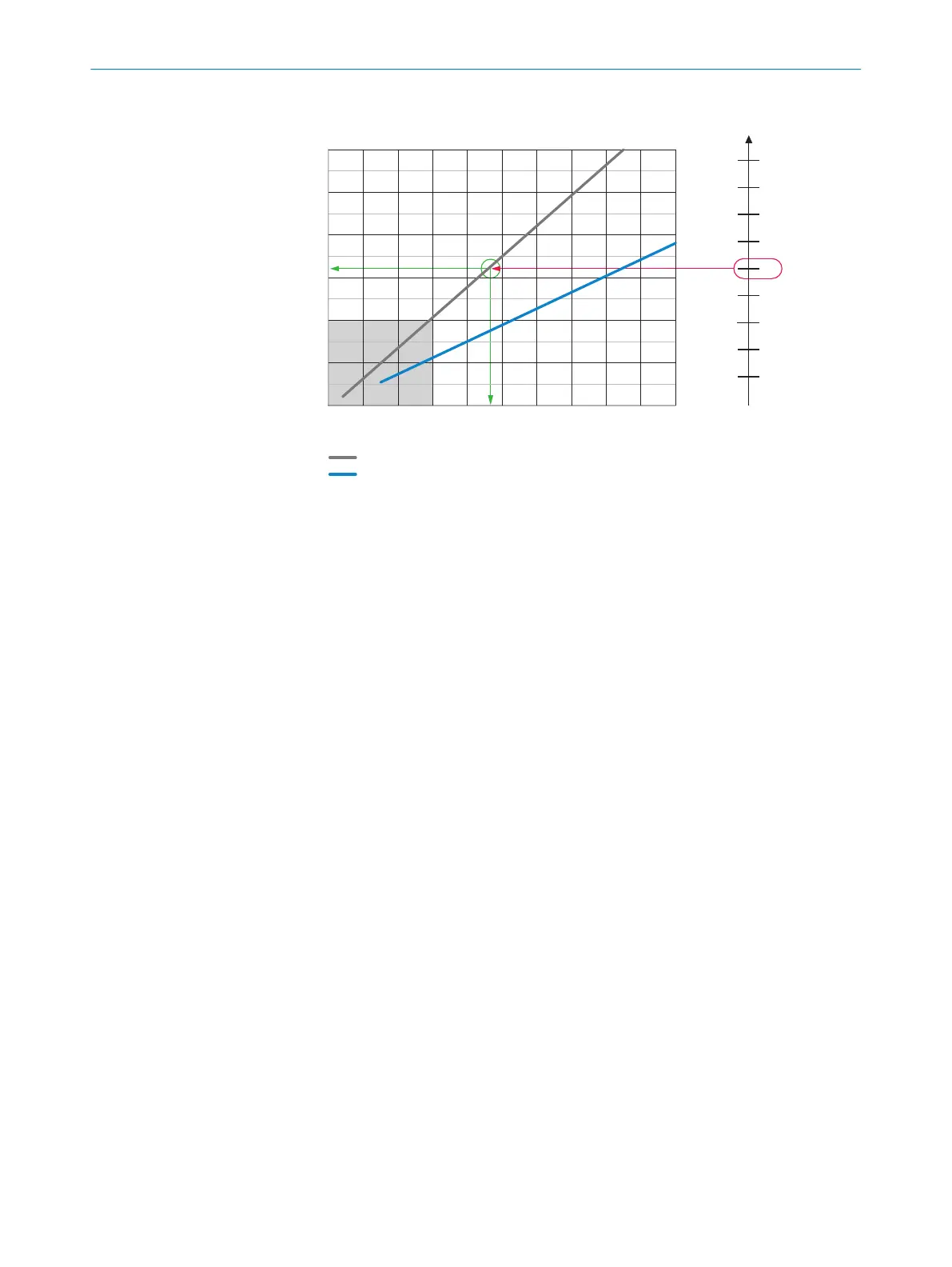
Figure 10: Interpretation aid for the field of view diagram
1
Field of view in mm
2
2
Complete area
3
Approximate resolution in mm/px
4
Working distance/Focus position in mm
5
Selected resolution
6
Focal length of lens, here example for f = 9.6 mm
7
Reading off: resultant maximum working distance
8
Reading off: resultant field of view (mm x mm)
Given (in red):
•
Resolution 5: approx. 0.5 mm/px
•
Focal length of lens 6: 9.6 mm
Read off (in green):
•
Maximum working distance 7: approx. 930 mm
•
Field of view 8: approx. 640 mm x approx. 510 mm
Both axes of the diagrams must be interpreted linearly.
5.4
Mounting the device
Aligning the device with viewing window to object
Align the device taking into consideration the field of view (see "Field of view diagrams",
page 23) and the application circumstances (see "Installation requirements", page 22).
Mounting the device
Perform one of the following steps:
•
Mount the device on a customer-supplied mounting system using at least 2 M5
screws of a suitable length. Screw the screws no more than 5 mm into the tapped
blind holes or sliding nuts of the device.
°
To do this, either use the tapped blind holes in the housing in pairs at the
front or below or use the two M5 sliding nuts in the lateral slots.
•
Attach the separately-ordered, optional SICK mounting system using the two slid‐
ing nuts on the device.
MOUNTING 5
8024439//2019-06 | SICK O P E R A T I N G I N S T R U C T I O N S | InspectorP621
25
Subject to change without notice