7
For CDB650-204: Connection cable 1:1 (female connector, M12, 17-pin, A-coded/male
connector, M12, 17-pin, A-coded)
For CDM420-0006: Adapter cable (female connector, M12, 17-pin, A-coded/male con‐
nector, D-Sub-HD, 15-pin)
8
Digital input/output 3
9
Digital input/output 4
ß
Digital input 2
à
Digital input 1, e.g., for connecting a trigger sensor
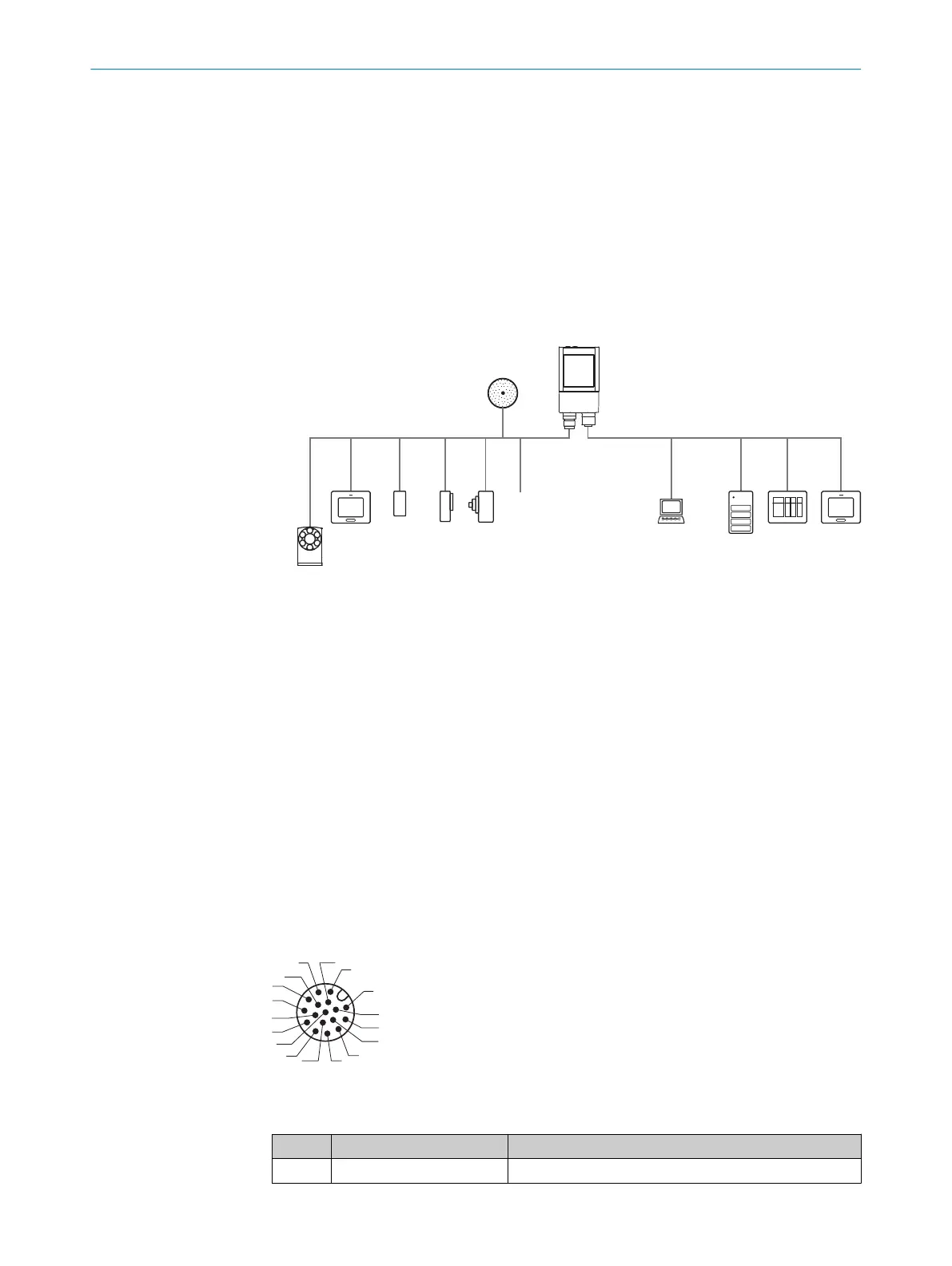
6.3.2 Example applications
Ethernet
InspectorP621
V
S
PC
FTP ß
SICK App StudioSICK App Studio
Programming 7
Image display 8
Diagnostics 9
HMI à
PLC 3
PLC 3
Digital
switching
inputs 5
Digital
switching
outputs 4
serial 2
EthernetSerial Data, CAN, I/O
CSN (CAN sensor
network) 1
External illumination 6
Figure 17: InspectorP621: connection options
1
CSN (CAN sensor network)
2
Serial
3
PLC (programmable logic controller)
4
Digital outputs, e.g. for signal lamps
5
Digital inputs e.g. for encoders, photoelectric sensors (trigger sensor)
6
External illumination unit, e. g. ICL
7
Programming
8
Image display
9
Diagnostics
ß
FTP server (image storage)
à
HMI interface
6.4 Pin assignments of electrical connections
“Power/Serial data/CAN/I/O” connection
3
1
7
2
6
5
4
8
13
14
17
15
9
10
12
16
11
Figure 18: Male connector, M12, 17-pin, A-coded
Table 5: Pin assignment of the “Power/Serial data/CAN/I/O” connection
Pin Signal Function
1 GND Ground
ELECTRICAL INSTALLATION 6
8024439//2019-06 | SICK O P E R A T I N G I N S T R U C T I O N S | InspectorP621
33
Subject to change without notice