Pin Signal at PC Function Wire color
4 – – –
5 GND Ground Black
6 ... 9 – – –
1)
Connect to the terminal “TxD Host” in the CDB/CDM connection module
2)
Connect to the terminal “RxD Host” in the CDB/CDM connection module
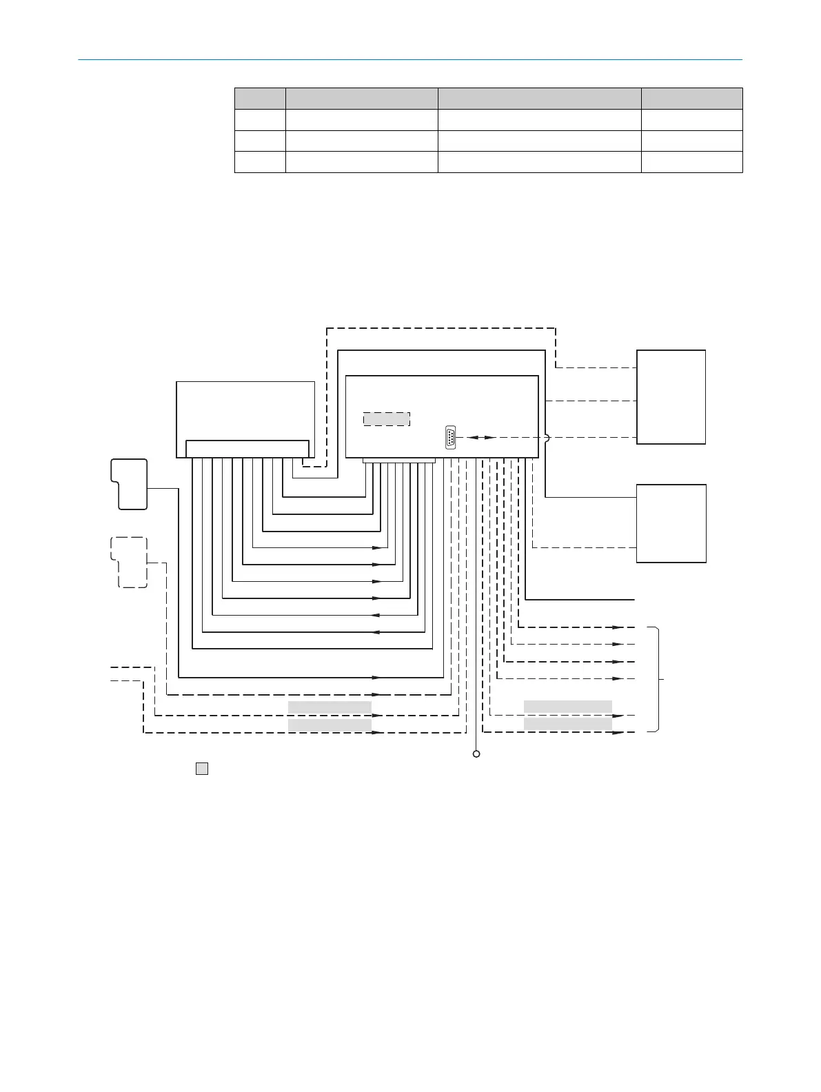
13.3 Connection diagrams of connection module CDB650-204
13.3.1 Connection of the device to CDB650-204
„V
S
”
“Host 1”
“Aux 1”
“Result 2”
“Result 3”
“Result 4”
“Result 1”
“CAN”
“Sensor 2”
“Sensor 1”
“AUX”
CAN bus
“Result 1”
“Result 2”
PLC
“Result 3”
“Result 4”
“External output 2
CDB650-204
Connection module 6
“Host 1”
“Aux 1”
RS-232
HOST/PLC
Further data
processing 8
PC
Configuration
Diagnostics
Image display
Interfaces 3
Device 2
“Ethernet” (Host 2/Aux 2), Image transfer 5
“USB” (Aux 3) 4, Image transfer 5
RS-232/RS-422
Ethernet
USB
“Host 2”
Ethernet
“Aux 2”
“Aux 3”
“Sensor 2”
“Sensor 1”
“External input 2”
“External input 1”
CMC600
1
ã
â
V
S
ß
= á
“External output 1”
à 9
7
Figure 25: Connection of the device to peripherals via CDB650-204 (overview)
1
External trigger sensor
2
Device
3
Interfaces
4
USB interface (not supported)
5
Image transmission
6
Connection modules
7
Configuration, diagnostics or image display
8
Data further processing
9
External digital outputs (not supported)
ß
Supply voltage V
S
à
External digital inputs (not supported)
ANNEX 13
8024439//2019-06 | SICK O P E R A T I N G I N S T R U C T I O N S | InspectorP621
55
Subject to change without notice