Device 1 CDM420-0006 Host
5
.
.
.
TD+
TD‒
RD+
RD‒
RD+
RD‒
TD+
TD‒
GND
GND
GND
11
12
1
5 8
9
6
7
6
24
T+
34
T‒/TxD
25
R+
35
R‒/RxD
36
GND
6
Shield
RS-422 RS-422
ON
OFF
S2 : RS 485
ON
OFF
S3: Term 422
S2
OFF
S3
OFF
120 Ω
2
3
3
1
7
2
6
5
4
8
13
14
17
15
9
10
12
16
11
110
15
6
11
5
5 4
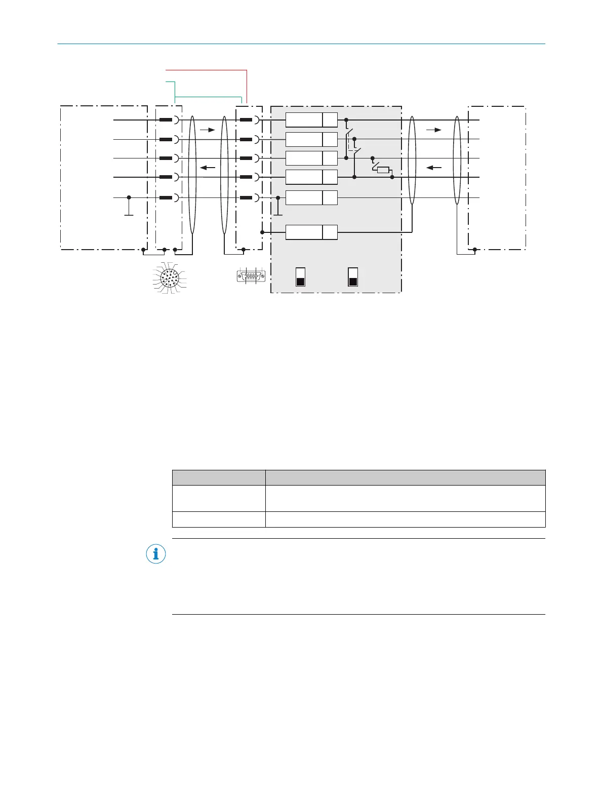
Figure 37: Connecting data interface RS-422 of the device in the connection module CDM420-0006
1
Device
2
Connecting cable for 15-pin male connector (not available)
3
Adapter cable (male connector, D-Sub-HD, 15-pin / female connector, M12, 17-pin, A-coded)
4
Connection module: female connector, D-Sub-HD, 15-pin
5
Male connector, M12, 17-pin, A-coded
Function of switch S3
Table 18: Switch S3: Term 422
Switch setting Function
ON Terminates the RS-422 receiver in the device to improve the noise ratio
on the line.
OFF No termination
NOTE
User of the RS-422 data interface:
•
Control the RS-422 data interface in the device with the API functions. In order to
activate the RS-422 data interface, use an installed SensorApp which contains
this function.
13.4.6 Wiring the CAN interface in the CDM420-0006
ANNEX 13
8024439//2019-06 | SICK O P E R A T I N G I N S T R U C T I O N S | InspectorP621
67
Subject to change without notice