8018061/2015-04-13• Subject to change without notice • SICK AG • Waldkirch • Germany • www.sick.com 3Lector
®
632 | SIcK
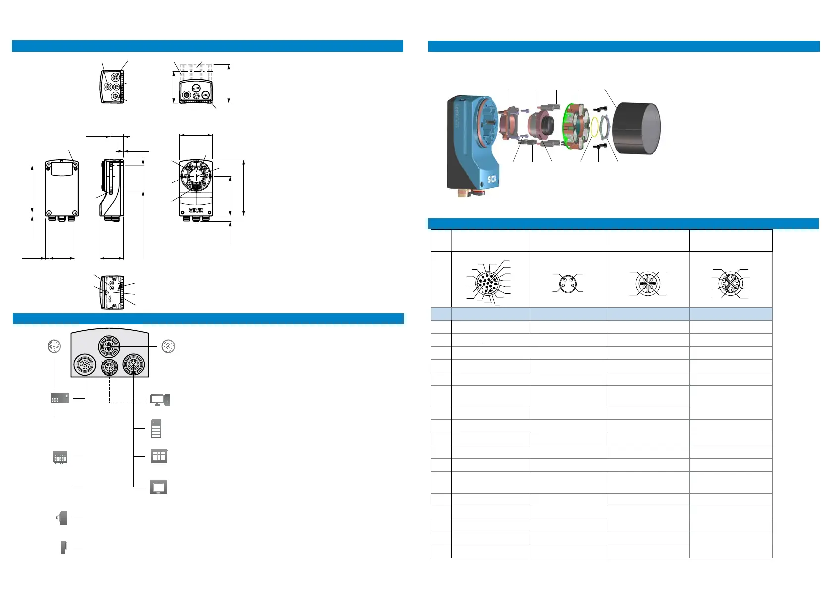
A. Dimensional drawings
59
(2.32)
45.8
(1.80)
min. 8 – max. 50
(0.31 – 1.97)
91.8
(3.61)
(0.23)
6.5
(0.26)
50
(1.97)
23.9
(0.94)
0.5
(0.05)
74
(2.91)
63.1
(2.48)
76.6
(3.02)
108
(4.25)
10.8
(0.43)
3
4
7
8
9
ß
å
æ
ç
ä
à
á
â
ã
1. External light connector
2. Gigabit Ethernet connector
3. USB connector
4. Power, serial, CAN and I/O connector
5. 23 mm protection hood for lens and lighting
6. 38 mm protection hood for lens and lighting
7. Plug to ensure IP67 for unused connectors
8. Blind hole thread M5, 5.5 mm deep (4 x)
9. Sliding nut M5, 5.5 mm deep (4 x)
ß Integrated lighting connector
à Aiming laser (2 x)
á S- or C-mount optical module
â Blind hole thread 2.5 mm (4 x) for mounting
integrated lighting
ã Optical axis and center of image sensor
ä Manual focus screw, hidden under cover/
sticker (S-mount Flex)
å Function button (2 x)
æ Bar graph LED display (5 x)
ç Removable cover for microSD card and
manual focus screw
è Status LED display (5 x 2 levels)
B. Connection diagram
24 V DC
Power I/O
USB
External light
Ethernet
External light
ICL
Connection
box
I/O
box
PC
FTP
HMI
PLC
Encoder
Photoelectric
switch
External light
VLR + CCS
FIeldbuses
1. External light (ICL)
2. Connection box
3. Fieldbuses
4. I/O box
5. 24 V DC, power source
6. Encoder
7. Photoelectric switch
8. External light (VLR + CCS)
9. PC
ß External FTP server
à HMI, operator interface
á PLC, control system
â Power cable, for example no. 2055419
(2 m)
ã Ethernet cable, for example no. 6034414
(2 m)
Power/SerialData/
CAN/IO
USB
(no image transfer)
External light Gb Ethernet
5
13
14
2
15
1
17
12
3
4
6
8
9
8
Pin Signal Signal Signal Signal
1 Ground +5V DC 24V switchable out TRD0_P
2
DC 24V +20% - Data - TRD0_N
3 CAN L + Data Ground TRD1_P
4 CAN H Ground - TRD1_N
5 TD+ (RS 422/485) TRD3_P
6 TD- (RS422/485)
TxD (RS 232)
TRD3_N
7 TxD (RS 232) TRD2_P
8 RxD (RS 232) TRD2_N
9 Sens GND
10 Input 1
11 RD+ (RS 422/485)
12 RD- (RS 422/485)
RxD (RS 232)
13 Input/output 3
14 Input/output 4
15 Input 2
16 Input/output 5
17 Input/output 6
D. Pin assignment
1. Optical module (C-mount)
2. Focus locking screws
3. Spacers
4. Integrated lighting
5. Protection hood
6. Metallic screws
7. Integrated lighting connector extension
8. Focus adjustment ring
9. Filter ring (replace with lter)
ß Black screws
à Filter holder
C. Optical conguration
Example with compact C-mount optics:
Note: parts vary between optical
congurations. To prevent focus
changes, x the C-mount lens with
at least one of the supplied screws
before starting operation.
1
3
5
6
4
7
8
2
9
ß
à
1
2
3
4
5
6
7
8
9
ß
à
á
â
ã
 Loading...