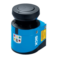
Laser Measurement Sensors of the LMS1xx Product Family
The SICK LMS1xx product family comprises electro-optical laser measurement sensors designed for a wide range of applications, providing robust and economical performance in various weather conditions. These sensors scan their surroundings in a plane using laser beams, measuring objects in two-dimensional polar coordinates by determining distance and direction from reflected laser pulses.
Function Description
The LMS1xx sensors operate on the principle of pulse propagation time measurement. They emit pulsed laser beams, and when a beam strikes an object, the reflection is detected by a photodiode in the sensor. The time taken for the pulse to return allows for distance calculation. The scanning takes place in a sector of up to 270°, providing a comprehensive view of the surroundings.
The LMS offers two primary modes of operation:
- Measurement of objects: This mode focuses on outputting raw measured distance values.
- Detection of objects with evaluation fields: This mode utilizes configurable evaluation fields to detect objects, suitable for applications like collision protection, building surveillance, or access monitoring.
The sensor can output measured values (raw data) using an electro-sensitive, active measurement technique, capable of measuring objects of almost any shape. It can also output measured values for a second reflected pulse, which is particularly useful in challenging conditions like rain or when measuring through a window.
Important Technical Specifications
The LMS1xx family includes several variants, each tailored for specific environments and functionalities:
- LMS100 (Indoor): IP 65 enclosure rating, no heating.
- LMS111 (Outdoor): IP 67 enclosure rating, with heating.
- LMS12x/LMS173 (Indoor, for object protection systems): IP 65 enclosure rating, no heating, optimized for object protection, features relay switching outputs and a digital sabotage output.
- LMS13x/LMS182 (Outdoor, for object protection systems): IP 67 enclosure rating, with heating, similar to LMS12x but for outdoor use.
- LMC12x (Indoor, for VdS object protection systems): IP 65 enclosure rating, no heating, VdS certified.
- LMC13x (Semi-outdoor, for VdS object protection systems): IP 67 enclosure rating, with heating, VdS certified.
- LMS151 (Outdoor, with extended functionality): IP 67 enclosure rating, with heating, offers an extended scanning range up to 50 m (164.04 ft) for objects with > 75% remission, and includes a CAN data interface with future support for CANopen 2.0A.
Common Specifications:
- Scan angle: Maximum 270°.
- Scanning frequency: 25 Hz or 50 Hz.
- Angular resolution: 0.25° or 0.50°.
- Remission: Detects objects with 10% remission.
- Distance measuring range: Up to 20 m (65.62 ft) for LMS100/LMS111/LMS12x/LMS13x/LMS173/LMS182/LMC12x/LMC13x with > 13% object remission (18 m with 10% remission). Up to 50 m (164.04 ft) for LMS151 with > 75% object remission (18 m with 10% remission).
- Hardware blanking window: Configurable from 1 to 15 m (3.28 to 49.21 ft).
- Laser protection class: Class 1 according to IEC 60825-1 (2007-3).
- Supply voltage: DC 10.8...30 V (LMS100/LMS111/LMS151) or DC 9...30 V (LMS12x/LMC12x/LMS13x/LMC13x/LMS173/LMS182).
- Power consumption: Max 20 W (without heating), max 60 W (with heating).
- Operating temperature range: 0°C to +50°C (32°F to +122°F) for indoor variants; -30°C to +50°C (-22°F to +122°F) for outdoor variants.
- Data interfaces: Ethernet (10/100 MBit, TCP/IP), RS-232 (serial host and auxiliary interfaces), CAN (10 Bit/s to 1 Mbit/s).
- Digital switching inputs: 2 inputs for activating evaluation cases or resetting outputs.
- Encoder inputs: 2 digital inputs for dynamic field adjustments based on speed.
- Digital switching outputs: 3 outputs (LMS100/LMS111/LMS151) for signaling evaluation field infringements or device readiness.
The beam diameter and distance between measured points increase with distance from the sensor. The beam diameter is always greater than the measured point spacing, ensuring full scanning without gaps. Minimum object size for reliable detection requires the laser beam to be fully incident on the object multiple times, meaning the object should be at least as large as the measured point spacing plus the beam diameter.
Usage Features
The LMS1xx sensors offer extensive configuration capabilities through the SOPAS ET configuration software. This software allows users to:
- Configure measurement properties, analysis behavior, and output properties.
- Create and save custom parameter sets.
- Perform system diagnostics.
- Monitor measured values and the measurement area in real-time (though the scan view in the monitor is dependent on PC computing power and may not be real-time).
Key configuration options include:
- Contamination measurement: The sensor continuously measures optics cover contamination. Users can choose strategies like "Inactive," "Highly available," "Available," or "Sensitive" to determine when contamination warnings or errors are triggered.
- Filters:
- Fog filter: Suppresses glare due to fog, reducing sensitivity in the near range (up to approx. 4 m).
- Hardware blanking window: Configures the LMS to only supply measured values from a specified distance, blanking out an area in front of the sensor.
- N-pulse-to-1-pulse filter: Filters out the first reflected pulse when two objects reflect pulses during a measurement (e.g., rain drops), allowing for measurement of the second reflected pulse.
- Particle filter: Filters out interference from dust, rain, or snow in dusty or wet environments.
- Mean filter: Forms and outputs the mean from a configured number of scans, reducing scan data output.
- Evaluation fields: Up to 10 configurable evaluation fields can be defined with various shapes (polygon, rectangular, reaching the LMS, at a distance from the LMS, dynamic). These fields are crucial for object detection applications.
- Evaluation strategies: Pixel evaluation, blanking, and contour monitoring.
- Obstruction protection: Prevents tampering due to shading or glare by switching the evaluation field if an object is in front of the laser output aperture or if the LMS is dazzled.
- Logical operators for inputs and outputs: Allows linking evaluation cases across multiple LMS sensors using AND or OR operators.
- Dynamic fields: The size of evaluation fields can change with speed measured by an encoder, useful for speed-dependent vehicle monitoring.
The LMS supports data communication using telegrams for requesting measured values, setting parameters, and querying status logs. Both ASCII and binary coding are supported for telegrams.
Mounting options:
- Direct mounting.
- Mounting with various mounting kits (1a, 1b, 2, 3) for adjustable alignment.
- Mounting with weather protection hoods (190° or 270°) for outdoor variants (LMS111/LMS13x/LMS151/LMS182).
- Quick-action mounting kits for easy replacement without re-adjustment.
When using multiple LMS sensors, it is recommended to arrange or shield them to prevent mutual interference, as sources with a 905 nm wavelength can cause interference if they act directly on another LMS.
Maintenance Features
The LMS laser measurement sensor is largely maintenance-free. However, regular cleaning of the optics cover is recommended, especially if it becomes contaminated.
Cleaning the optics cover:
- Use a clean, soft brush to remove dust.
- Wipe the view window with a clean, damp cloth.
- Avoid aggressive or abrasive detergents.
- For anti-static cleaning, SICK offers an anti-static plastic cleaner (part no. 5600006) and a lens cloth (part no. 4003353).
Exchanging an LMS:
The design with external cable connections ending in system plugs or plug connectors simplifies device replacement. When replacing an LMS:
- Switch off the voltage supply.
- Remove connection cables.
- Mount the replacement device.
- Configure the new device using SOPAS ET.
The housing screws of the LMS are sealed, and opening the housing by unauthorized personnel will void warranty claims.
Troubleshooting:
The LMS provides error displays via LEDs and a 7-segment display for diagnostics.
- LEDs: Indicate operational status (e.g., in operation, event signaled, optics cover contaminated, switching output switched, teach-in mode) and error conditions.
- 7-segment display: Used for diagnostics of occurring errors or malfunctions, providing indications like "No error," "IDLE mode," "Motor starts," or "LMS faulty."
- Detailed error analysis: Communication errors return error codes, and status errors during a scan are written to a status log. The SOPAS ET software includes a "Field evaluation monitor" and "Field evaluation logging" for in-depth analysis of evaluation field infringements and LMS operation.
The LMS is designed for minimal environmental impact, consuming low power. Unserviceable or irreparable devices should be disposed of in compliance with local/national waste disposal regulations, with electronic assemblies handled as hazardous waste. SICK AG does not accept returned unusable or irreparable devices.