Operating Instructions
LMS1xx Laser Measurement Sensors
Electrical installation
8012471/ZN27/2017-06-09 © SICK AG · Germany · All rights reserved · Subject to change without notice 67
Chapter 6
Destruction of the device!
Connecting the sensor incorrectly can lead to the destruction of the device.
Connect the supply voltage for the sensor correctly. Reverse connection is not
permitted.
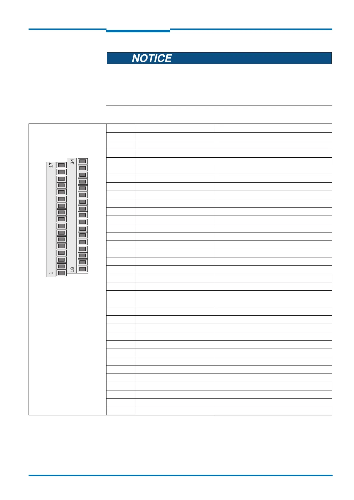
Terminal Signal Function
1 Reserved Do not use!
2 Reserved Do not use!
3 RxD HOST Receiver RS-232 (host interface)
4 Reserved Do not use!
5 Reserved Do not use!
6 IN1 Switching input 1
7 GND IN1 Ground switching input 1
8 IN2 Switching input 2
9 GND IN2 Ground switching input 2
10 INC1 A Input encoder 1, contact A
11 INC1 B Input encoder 1, contact B
12 GND INC1 Ground encoder 1
13 OUT1 A Switching output 1, contact A
14 OUT1 B Switching output 1, contact B
15 OUT1 R Switching output 1, resistor monitored
16 OUT2 A Switching output 2, contact A
17 OUT2 B Switching output 2, contact B
18 GND Ground Sensor
19 V
S
Power Supply Sensor
20 TxD HOST Transmitter RS-232 (host interface)
21 Reserved Do not use!
22 GND RS/CAN Ground RS-232/CAN
23 CAN H CAN bus high
24 CAN L CAN bus low
25 V
S
CAN
1)
Power supply CAN bus
26 GND RS/CAN Ground RS-232/CAN
27 CAN H CAN bus high
28 CAN L CAN bus low
29 V
S
CAN
1)
Power Supply CAN bus
30 OUT3 R Switching output 3, resistor monitored
31 OUT3 B Switching output 3, contact B
32 OUT3 A Switching output 3, contact A
33 OUT2 R Switching output 2, resistor monitored
34 Shield Housing/shield
Tab. 19: LMS10x: Terminal assignments (2 x terminal blocks, 17-pole)
1) DC 24 V