Electrical installation
68 © SICK AG · Germany · All rights reserved · Subject to change without notice 8012471/ZN27/2017-06-09
Operating Instructions
LMS1xx Laser Measurement Sensors
Chapter 6
Important The OUT1 B, OUT2 B and OUT3 B connections are internally connected to each other.
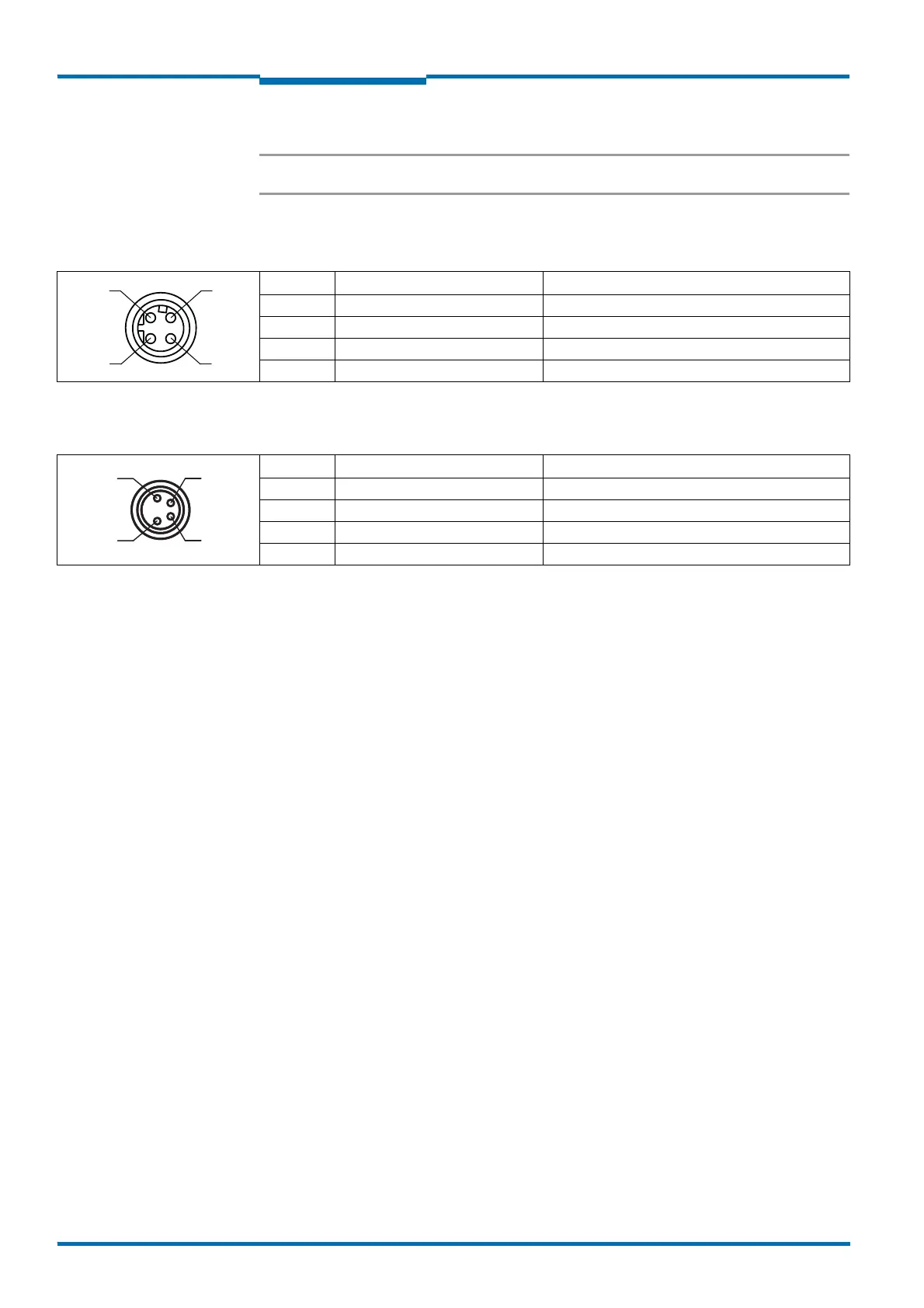
“Ethernet” connection
“AUX” connection
Pin Signal Function
1 TX+ Transmitter+
2 RX+ Receiver+
3 TX– Transmitter–
4 RX– Receiver–
Tab. 20: LMS10x: Pin assignment of the “Ethernet” connection (4-pin M12 female connector, D-coded)
Pin Signal Function
1 Reserved Do not use!
2 RxD AUX Receiver RS-232 (auxiliary interface)
3 GND RS Ground RS-232
4 TxD AUX Transmitter RS-232 (auxiliary interface)
Tab. 21: LMS10x: Pin assignment of the “AUX” connection (4-pin M8 female connector)