The USB connection (USB 2.0 Mini-B, female connector) may only be used temporarily
and onl
y for configuration and diagnostics.
4 Changing position of the system plug
Changing the position of the system plug:
B
T
he system plug is installed at the bottom or rear when the safety laser scanner is
delivered. You can change the position of the system plug if needed.
Tool required:
•
T
X20 Torx wrench
Approach
1. Loosen the screws of the system plug.
2. Carefully remove the system plug from the safety laser scanner.
3. Loosen the cover plate screws.
4. Remove the cover plate from the safety laser scanner.
5. Carefully slide the new system plug into the safety laser scanner at the desired
position (bottom or rear).
6. Screw in the system plug using the captive screws. Tightening torque: 2.25Nm …
2.75Nm.
7. Install the cover plate on the safety laser scanner. Tightening torque: 2.25Nm …
2.75Nm.
5 Mounting the safety laser scanner directly
Direct mounting:
C
T
he safety laser scanner has 4 M5 threaded holes on the back. If you are able to drill
through the mounting surface from the rear, you can mount the safety laser scanner
directly using these threaded holes.
b Use either the rear 1 or the side 2 M5 threaded holes for direct mounting.
b
Use all four rear or all four side M5 threaded holes for direct mounting, so that the
values given in the data sheet for vibration and shock resistance are achieved.
b
Maximum depth of thread engagement: 7.5mm.
b
Tightening torque: 4.5Nm to 5.0Nm.
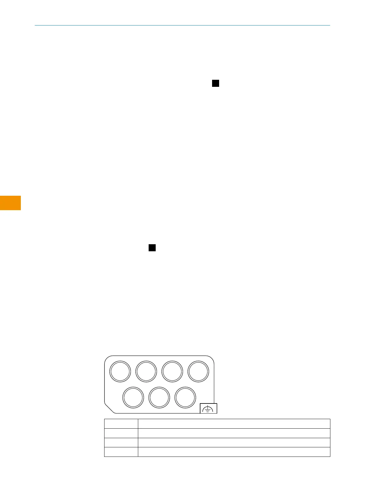
6 Connection overview
MICSX-CAAAMDMD1 (part number: 2115434)
XD1 XF1 XF2 XG1
XG2 XG4 XG3
XD1 Voltage supply
XF1, XF2 Ethernet for EFI-pro, data output, configuration, and diagnostics
XG1 Local inputs and outputs 1
XG2, XG3 Dynamic control inputs
MOUNTING INSTRUCTIONS
14
M O U N T I N G I N S T R U C T I O N S | microScan3 Pro I/O 8026187/1H7G/2022-10-19 | SICK
Subject to change without notice
en
 Loading...


