12
SICK MSL
8 007 653/09-04-01 Technical Description • MSL © SICK AG • Safety Systems • Germany • All rights reserved
5.3 Distance from
reflective surface
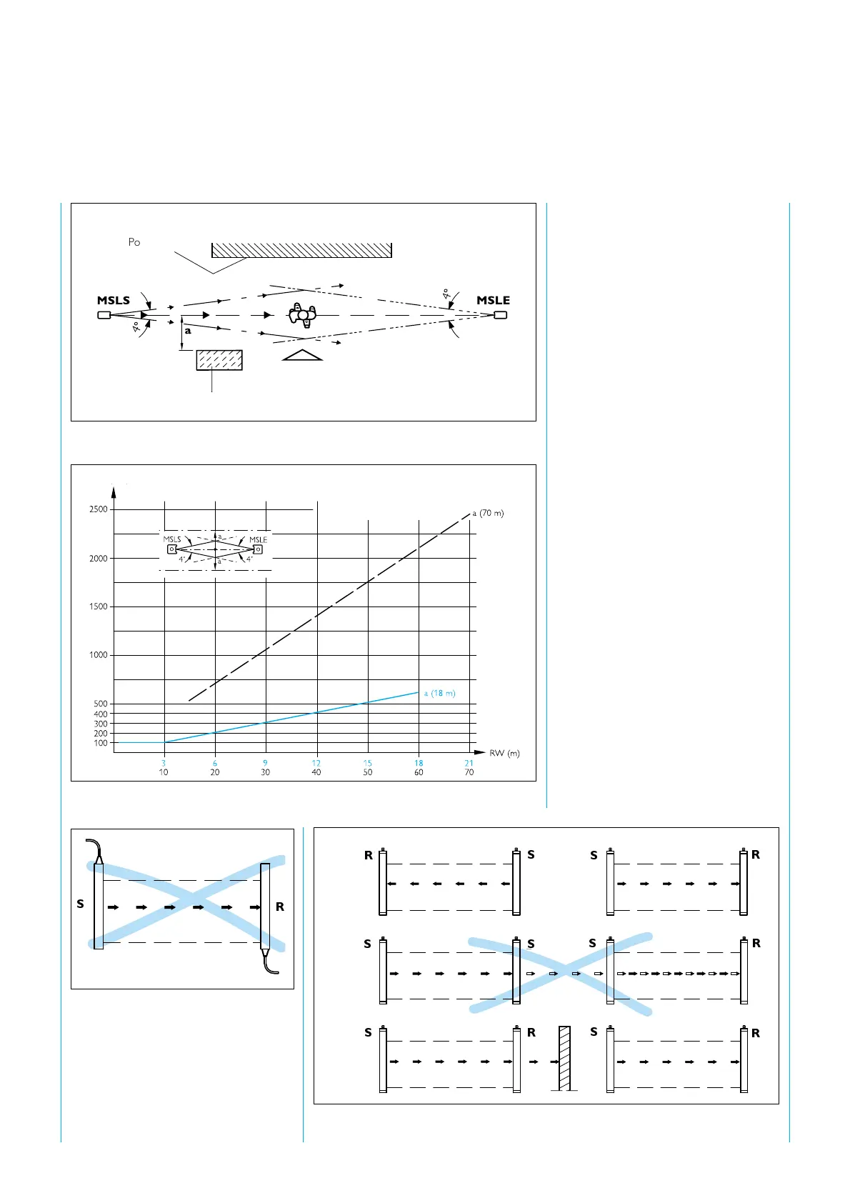
Reflective surfaces located (placed
or fixed) within the sender and
receiver range, may cause reflection
and thus prevent an obstacle from
being reliably detected.
For this reason, a minimum distance
"a" from reflective surfaces to the
optical axis (linear connection
between MSLS and MSLE) must be
maintained (see
fig. 9
). The
distance "a" is dependent on the
distance between the sender and
receiver (
fig. 10
).
5.4 Multiple
safeguarding
If two MSL units are used per
guarding system, it must be ensured
that the two units cannot influence
each other. Since the light beams
diverge, their cross-section becomes
greater as the distance between the
MSLS and the MSLE increases. The
light beams from the sender unit
may only be received by its
accompanying receiver unit. To
eliminate any muttual influence, it
must be ensured that they are
positioned correctly during
installation (
fig. 11 and 12
).
Fig. 10: Necessary safety distance (a) in relation to the distance between sender and
receiver units.
Fig. 9: Correct assembly, correct alignment, no diverted reflection
Fig. 11: The sender and receiver must be
installed in the same direction, installation
rotated by 180° is not permitted.
R
S
Point-of-operation
boundary
Reflective surface
Distance a in mm
Fig 12. Installation of two MSL systems in series: with different beam directions (above), with
wall between two systems (below)
R
R
R
R
R
R
S
S
S
S
S
S
S