9
SICK MSL
8 007 653/09-04-01 Technical Description • MSL © SICK AG • Safety Systems • Germany • All rights reserved
The MSL should be mounted such
that upon interruption of the light
beam, the dangerous location can
only be reached if the dangerous
condition of the machine has been
neutralised. The requirement for this
is that there is a safety distance
between the light beams and the
nearest point of danger.
This safety distance is defined as per
EN 999 (see
5.2 Safety distance for
dangerous zones
).
Persons situated inside the danger
zone, but outside the protection
field are not recognised. It must
therefore be ensured that a dan-
gerous condition is only possible
when there is nobody present in
the danger zone.
The relevant legal and government
regulations are to be complied with
for the implementation of protec-
tion installations. These regulations
vary, depending on areas of appli-
cation.
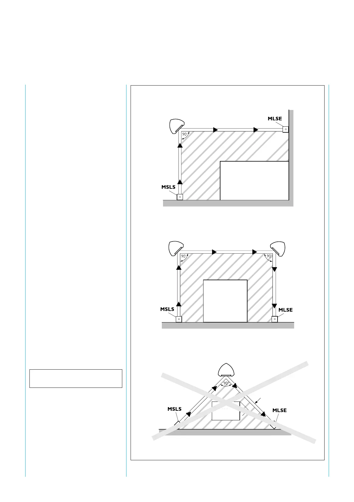
4.3 Corner mirrors and
columns
When the MSL is used in conjunc-
tion with one or two corner mir-
rors, 2 or 3 sides can be protected
respectively (
fig. 6
). Use of mirrors
reduce the scanning range e. g. for a
device with normal scanning range
of 70 m the range is reduced to
approx. 61 m for 2 mirrors
approx. 42 m for 4 mirrors
Fig. 6: Multi-sided access control to danger zones with MSL multi-beam safety light barrier.
Machine
Machine
Machine
Safety gap too
small
Spiegelsäule
Mirror column
Mirror column
Mirror column
Mirror column