8014954/ZOZ7/2017-09-05 • Subject to change without notice • SICK AG • Waldkirch • Germany • www.sick.com 2RFH6XX | SICK
2 M6 screws. Screw in the M6 screws to max.
6.5 mm into the threaded mounting holes ( see
“Device layout” on page 6).
3. Align the surface of the integrated antenna on
the RFH630 (front face) and where applicable the
external antenna of the data card (transponder)
to the object. In doing so, pay attention to the
form, alignment, and dimensions of the antenna
elds (internal antenna: ( see “Reading eld
diagrams RFH630” on page 7). Avoid any
large metal surfaces positioned to the front as far
as possible.
4. Ensure that no electrically conductive objects,
such as metal objects, are positioned between
the RFH630/external antenna and the transpon-
der during the read/write process. This would
attenuate the generated HF eld and thereby
reduce the scanning range of the RFH630.
Scanning range of the read/write eld on the
RFH630
The maximum scanning range for communication
between the RFH630 and transponder depends
on various factors. Primarily, the dimensions of the
transponder's antenna positively aects the scanning
range. An additional factor for the scanning range
is the quality of the transponder, for example, the
antenna gain, the integrated transponder IC, and its
associated sensitivity. The specic reading eld dia-
grams are available on the product pages (www.sick.
com) for the individual transponders. The diagrams in
this Quickstart depict the associated reading ranges
for three dierent transponders ( see “Reading eld
diagrams RFH630” on page 7).
Important!
The specied values can only be achieved if the tran-
sponder is aligned parallel and evenly to the RFH630
antenna.
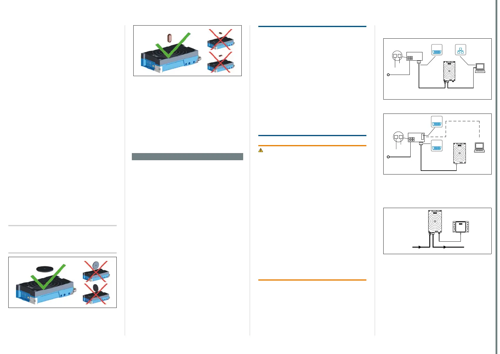
Fig. 1: Optimal alignment of discs, coins, and ISO cards to
the RFH630
Fig. 2: Optimal alignment of on-metal transponders and
glass transponders to the RFH630
CDB620-001 connection module
Mount the CDB620-001 connection module in
the vicinity of the RFH630. If you are using the
serial data interfaces (RS-232), we recommend a
max. distance of 3 m. Mount the CDB620-001 in
such a way that the device remains accessible at
all times. See also CDB620-001 connection
module operating instructions (no. 8012119).
- See “Sources for obtaining additional informa-
tion” on page 5
.
Step 2: Electrical installation
• The electrical installation must only be per-
formed by electrically qualied persons.
• Standard safety requirements must be met when
working in electrical systems.
• Electrical connections between the RFH630 and
other devices may only be created or disconnected
when there is no power to the system. Otherwise,
the devices may be damaged.
• When using connecting or extension cables with an
open end, make sure that bare wire ends are not
touching (risk of short-circuit when the supply volt-
age is switched on). Wires must be appropriately
insulated from each other.
• Wire cross-sections in the supply cable from the
customer's power system must be designed in
accordance with the applicable standards. 0.8 A
protection at the start of the feeding supply circuit
when the RFH630 is operated without a connection
module using a SICK cable.
• The power supply via a power supply unit must be
capable of buering a brief power failure of 20 ms.
• All circuits connected to the RFH630 must be de-
signed as SELV circuits. The power supply or power
supply unit must satisfy SELV requirements in ac-
cordance with the currently applicable EN 60950-1.
(SELV = Safety Extra Low Voltage).
NOTE
Risk of damage to the RFH630 due to possible
short-circuit!
The supply voltage input in the RFH630 is designed
with internal circuit protection to provide reverse po-
larity protection. The internal functional earth, which
also corresponds to the negative pole of the RFH630,
has a direct connection to the metal housing of the
RFH630 due to reasons relating to high frequency.
If the supply voltage has the incorrect polarity, this will
not cause any damage provided that the RFH630 is
not connected (by
• either other cables or
• its housing)
to other peripheral devices that use the same ground-
ing point.
WARNING
Risk of injury and damage caused by electrical
current!
The RFH630 is designed to be operated in a system
with professional grounding of all connected devices
and mounting surfaces to the same ground potential.
As a result of equipotential bonding currents between
the RFH630 and other grounded devices in the
system, faulty grounding of the RFH630 can have the
following consequences:
• Metal housings are vulnerable to dangerous cur-
rents
• Malfunction and destruction of devices
• Damage to the cable shields caused by heating,
resulting in cable res.
Ensure that the ground potential is the same at all
grounding points. See the “Electrical installation”
chapter in the RFH630 technical information for
measures to eliminate hazards.
If the cable insulation is damaged, disconnect the
power supply immediately and have the damage
repaired.
1. Connect the communication interface (e.g., Ether-
net) of the RFH630 directly to the PC.
EthernetEthernet
CDB620-001
(optional)
SOPASSOPAS
RFH630-1102101
1
2
V
GND
Configuration
Diagnostics
Ethernet
(AUX, HOST)
e.g. cable
e.g. cable
SerialSerial
...
...
PC
Power/
Serial Data/
CAN/I/O
(AUX, HOST)
DC 10 V ... 30 V
Fig. 3: RFH630-1102101 electrical connection block dia-
gram for commissioning in the default conguration
Connection Module
CDB620-001
(optional)
SOPASSOPAS
RFH630-1000001
1
2
to 30 V
GND
Configuration
Diagnostics
SerialSerial
...
...
Power/Serial Data/
CAN/I/O
(AUX, HOST)
PC
e.g. cable
no. 2014054 (2 m)
DC 10 to 30 V
SerialSerial
Fig. 4: RFH630-1000001 electrical connection block dia-
gram for commissioning in the default conguration
2. If an external antenna is being used (e.g.,
RFA332-2032, no. 1054399), connect it to the
antenna connection on the RFH630-1102101.
RFH630-
1102101
HOSTPower
RFA332-2032
Fig. 5: RFH630-1102101 with RFA332-2032 external
antenna
3. If necessary, connect a read pulse sensor, such
as a photoelectric sensor, to the “IN 1” switching
input of the CDB620-001.
4. Supply power to the RFH630.
After successful initialization, the “Ready” LED
illuminates green.
 Loading...


