8014954/ZOZ7/2017-09-05 • Subject to change without notice • SICK AG • Waldkirch • Germany • www.sick.com 3RFH6XX | SICK
Step 3: Conguration with PC
In case of error, the SOPAS ET conguration software
is used by default to adjust the RFH630 parameters
to the application and to the diagnostics.
a. Installing and starting the SOPAS ET
conguration software
1. Download and install the software from the rel-
evant SICK product page on the Internet at
www.sick.com/SOPAS_ET:
• Latest version of the conguration software
• Current device description le (*sdd) for the
RFH630.
2. For the conguration software, select the
“Complete” option as selected by the installation
wizard. Administrator rights may be required on
the PC to install the software.
3. Start the “SOPAS ET” program option after com-
pleting the installation. Path: Start > Programs >
SICK > SOPAS ET Engineering Tool > SOPAS.
4. Establish a connection between SOPAS ET and
RFH630 via the automatically opened wizard. To
do so, select the RFH630 under the devices avail-
able depending on the connected communication
interface, e.g., Ethernet.
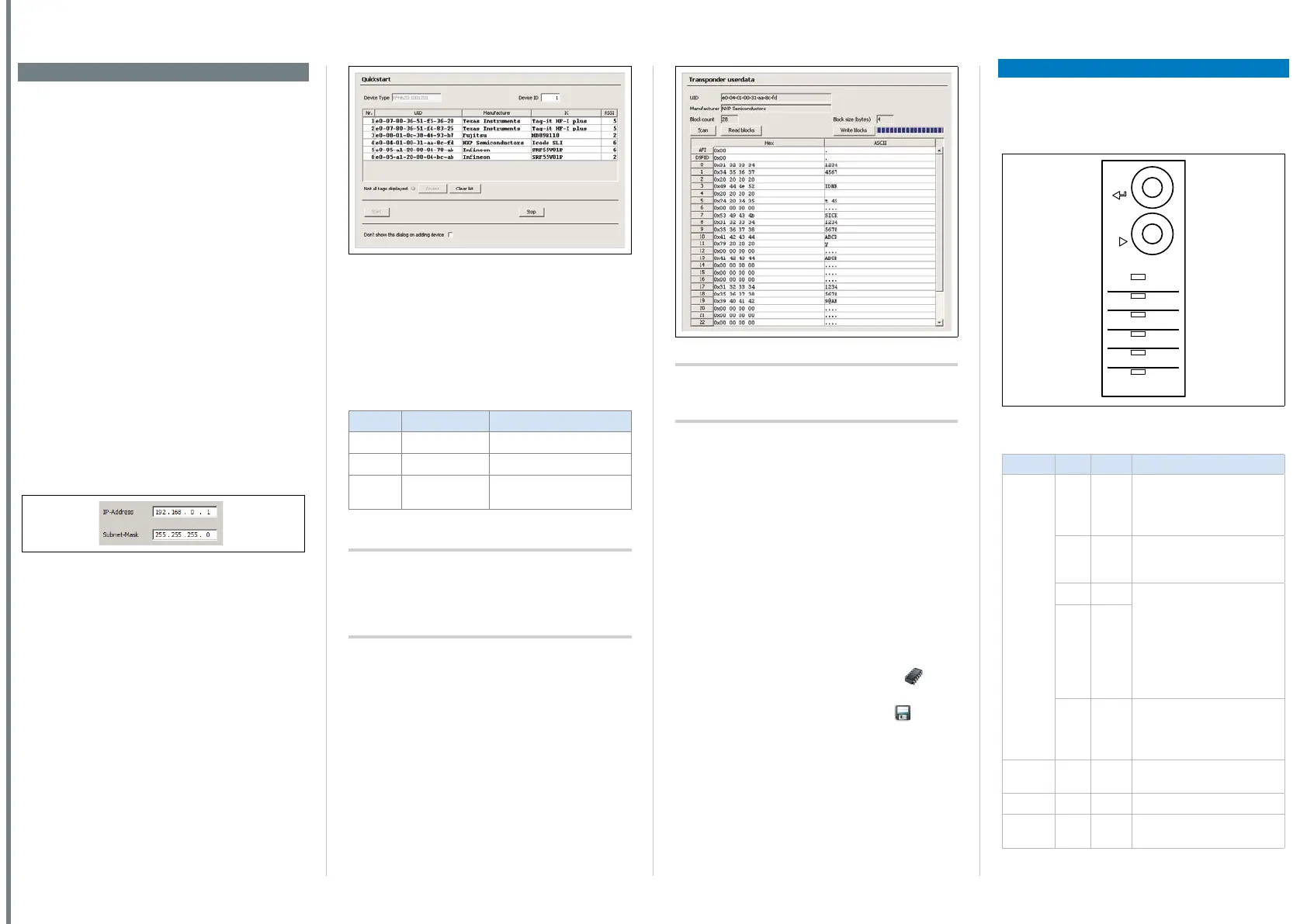
5. The following IP address is congured by default
on the RFH630-1102101:
Fig. 6: Default IP address
6. SOPAS ET establishes communication with the
RFH630 and loads the associated device descrip-
tion le for the RFH630. The Quickstart tab opens.
b. Identifying a transponder in Quickstart
mode
1. Bring one or more standards-compliant HF tran-
sponders into the working area of the internal an-
tenna or, where applicable, the external antenna
of the RFH630.
2. Click the “Start” button in the Quickstart tab in
SOPAS ET. SOPAS ET generates read pulses
continuously and lists the identied transponders
one after the other in the Quickstart window.
Fig. 7: SOPAS ET: Display of six identied transponders in the
Quickstart window
Feedback about transponder detection in the HF
eld
In Quickstart mode, the default signal of the process
feedback LED indicates whether an HF eld is present
and transponders have been detected. The process
feedback LED is in the center of the RFH630 front
plate and lights up blue.
PF LED Condition Status
O
ON HF eld available
Ö
Flashing slowly 1 transponder in eld
Ö
Flashing rapidly More than 1 transponder
in eld
O = illuminated; Ö = ashing
Tab. 1: Process feedback LED
Important!
The automatic triggering in Quickstart mode is
intended for initial commissioning and not for per-
manent use when operating the RFH630 under real
conditions.
c. Accessing the data on a transponder
1. In order to access the memory area of a tran-
sponder, click the stop button in Quickstart.
2. Highlight the desired transponder (click it with the
mouse).
3. Click the transponder access button. The tran-
sponder user data tab displays the content of the
selected transponder.
Fig. 8: SOPAS ET: transponder user data display window
Important!
The UID (Unique Identier) of the transponder cannot
be changed.
d. Continuing the conguration
1. Under SOPAS ET in the left-hand navigation tree,
edit the required tabs for the application using
the additional entries under parameters. These
include transponder processing, object trigger
control (e.g., via “Sensor 1” switching input), data
processing and output, data output interface(s),
and the function of the switching inputs and
outputs.
2. Test and, if necessary, modify the settings made
when operating the system under real conditions.
e. Completing the conguration
Permanently save the entire conguration once it
has been successfully tested:
Parameter set in the RFH630: Click the
but-
ton.
Conguration le on the PC: Click the
button.
Device description
Device layout
- See “Device layout” on page 6.
Status indicators
Ready
Result
LNK TX
CAN
Data
RF
Read Diagn
Antenna
Sync
Userdef.
TeachIn
Enter
Stop
Fig. 9: Optical status indicators
Status indicators on the rst display level
Display LED Color Status
Ready
O
Green Lights up constantly after
switching on and completion
of successful self-test (device
ready)
– Goes out when downloading
or uploading conguration
data from and to the RFH630
Ö
Green PROFINET IO operation (single
port): Flashes cyclically red
(long) and green (short)
alternately.
Trying to establish a connec-
tion to a PLC (IO controller)
or loss of connection during
operation
Ö
Red
Ö
Red New rmware installation after
download to RFH630.
Do not turn o the supply
voltage!
Result
O
Green Successful read process
(good read, 100 ms)
RF
O
Green HF eld is switched on
Data
Ö
Yellow Data transmission via host
interface
 Loading...


