8.3 Logic Editor
The logic Editor of SIG200 is a key function allowing you to realize dedicated applica‐
tions within the device by utilizing connected sensors or actuators.
NOTE
The drag & drop Logic Editor configuration is not accessible via the fieldbus or the REST
API. There, only process data can be used as input or output values for the Logic Editor.
The Logic Editor can use all available signal inputs as sources for the logic application.
In SIG200 this includes:
•
All IO-Link port pins configured as “Digital Input”
•
IO-Link Process Data In from all SX port pins 4 configured to IO-Link mode (Port
S1-S4)
•
Fieldbus Input Process Data
•
REST API Input values
The Logic Editor can use all available signal outputs as sinks for the logic application.
In SIG200 this includes:
•
All IO-Link port pins configured as “Digital Output”
•
IO-Link Process Data Out from all port pins 4 configured to IO-Link mode (Port S1-
S4)
•
Fieldbus Output Process Data
•
REST API Output values
NOTE
It is necessary to upload and assign the IODDs of the devices to be used in the Logic
Editor.
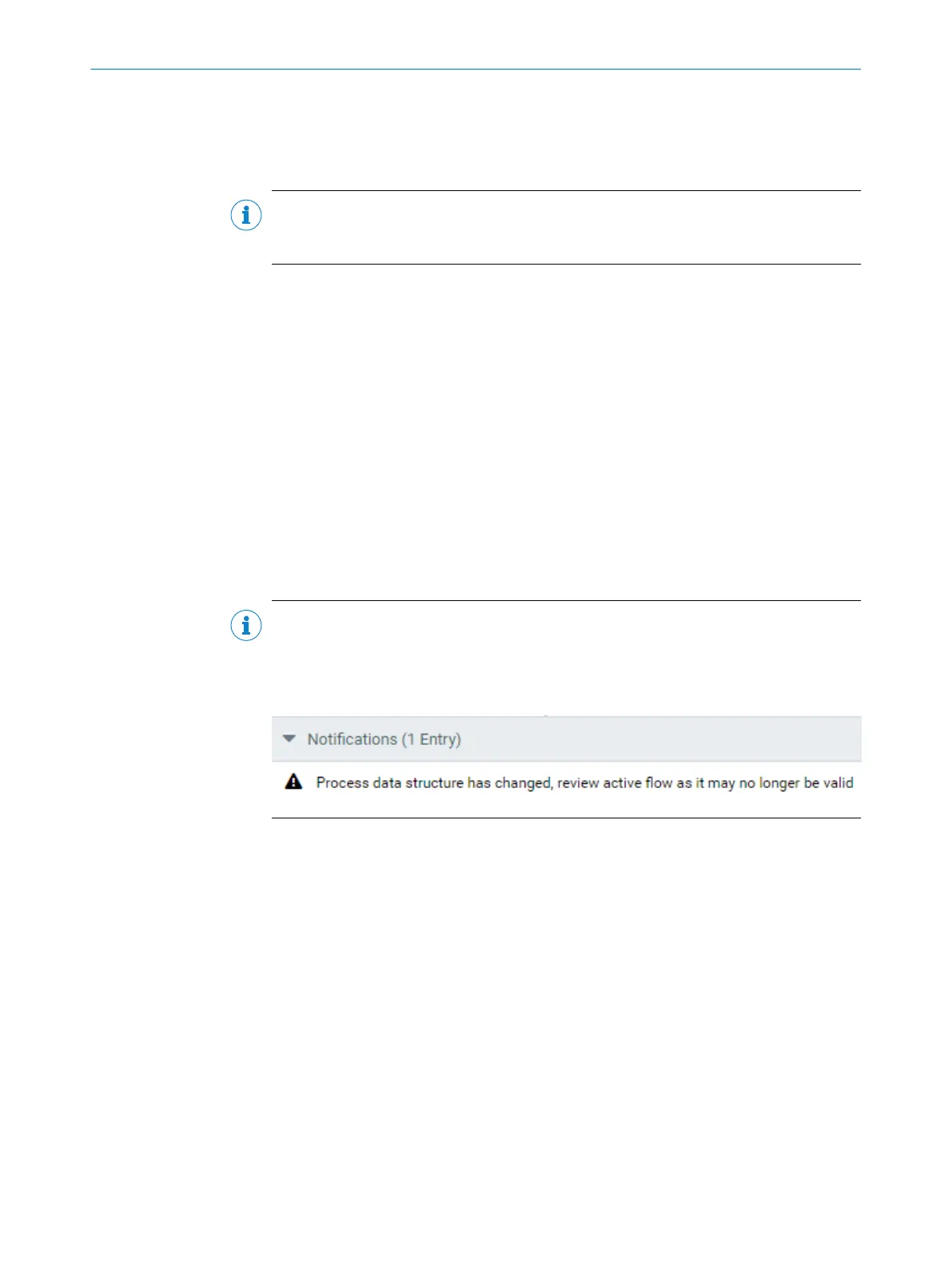
Removing IODDs of devices which has been connected in the Logic Editor could lead to
incompatibilities. This is indicated by the following notification:
8 DEVICE FUNCTIONS
76
O P E R A T I N G I N S T R U C T I O N | Sensor Integration Gateway - SIG200 8017853/2019-06-06 | SICK
Subject to change without notice

 Loading...

