Do you have a question about the SICK UE 402 and is the answer not in the manual?
Explains the purpose and scope of the operating instructions.
Identifies the intended audience for the operating instructions.
Outlines the topics covered in the operating instructions.
Lists and defines technical abbreviations used in the document.
Explains the meaning of symbols and icons used in the document.
Defines symbols for sender and receiver in diagrams.
Explains the meaning of "dangerous state" in the context of machine safety.
Defines the qualifications required for personnel installing/servicing the device.
Describes how the UE 402 extends the capabilities of the C 4000 safety light curtain.
Specifies the intended use and conditions for the UE 402 to maintain warranty.
Provides essential safety notes and procedures for correct and safe operation.
Discusses environmental considerations and proper disposal of the device.
Highlights key functionalities and extensions provided by the UE 402.
Explains how the UE 402 processes signals and interacts with connected systems.
Introduces functions of the C 4000 selectable via software with the UE 402.
Details the bypass function, its activation, and limitations.
Explains the Presence Sensing Device Initiation mode and its operation.
Defines the specific area within the protective field for PSDI interpretation.
Explains how machine cycle contacts are used in PSDI mode.
Describes the three supported start sequences for PSDI mode initiation.
Explains the two methods for releasing PSDI control (Limited and Not limited).
Describes the function of run-on monitoring for detecting brake failure.
Details the eccentric press mode and its muting behavior.
Explains the teach-in function and its connection to the UE 402.
Introduces the ability to configure up to six operating modes via CDS.
Explains how function scope depends on cascade or application settings.
Lists combinations of functions that cannot be used together.
Describes the diagnostic LED on the UE 402 and its status indications.
Outlines the necessary steps after mounting and installation of the UE 402.
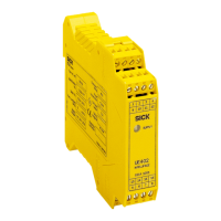
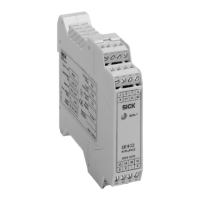
Shows the terminal layout and connections for the UE 402.
Explains the connection and use of the operating mode selector switch.
Details the connection and configuration of the key-operated pushbutton for bypass.
Describes the connection of the teach-in key-operated switch to the UE 402.
Lists necessary machine cycle contacts for PSDI mode and their requirements.
Emphasizes the need for qualified personnel and checks before initial operation.
Outlines the necessary steps and tools for preparing the configuration process.
Provides initial steps and procedures for dealing with identified faults.
Advises on contacting SICK Support if errors cannot be resolved.
Explains the meaning of diagnostic LED displays and how to remedy errors.
Details additional error messages from the 7-segment display for the C 4000.
Explains how to use CDS software for in-depth diagnostic analysis.
Presents detailed technical data and specifications of the UE 402.
Provides a detailed dimension drawing of the UE 402 unit.
Lists the contents of the UE 402 product delivery.
Lists available accessories and their corresponding part numbers.
Contains the EC Declaration of Conformity for the UE 402 product family.