Operating Instructions Chapter
8 009 874/31-03-03 © SICK AG • Industrial Safety Systems • Germany • All rights reserved
21
?!1
The machine/system could inadvertently start up while you are connecting the unit.
Make sure that the entire machine/system is disconnected during the electrical
installation.
The UE 402 meets the interference suppression requirements (EMC) for industrial use
(interference suppression class A). When used in residential areas it can cause inter-
ference.
The control cabinet or assembly housing of the UE 402 must at least comply with
enclosure rating IP 54.
You must connect the UE 402 to the same external voltage supply as the safety light
curtain.
The external voltage supply of the device must be capable of buffering brief mains
voltage failures of 20 ms as specified in EN 60204-1. Suitable power supplies are
available as accessories from SICK (Siemens type series 6 EP 1).
If the signal transmitters (e.g. operating mode selector switch, teach-in key-operated
switch, etc.) are mounted in control panels outside the installation, you must protect the
corresponding connecting cables from short and cross-circuiting, e.g. by installing them
in suitable cable conduits.
'
WARNING
.
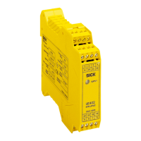
the UE 402
1234
5678
9
10
12
11
13
14
16
15
Terminal strip I
Terminal strip II
Terminal strip III
Terminal strip IV

 Loading...